
Device for smooth sliding of a positioning rod of a sawing device platform

a positioning rod and device technology, applied in the field of sawing device platforms, can solve the problems of inconvenient use and high cos

Inactive Publication Date: 2005-02-15
YU SHI WHI
View PDF9 Cites 70 Cited by
  • Summary
  • Abstract
  • Description
  • Claims
  • Application Information

AI Technical Summary

Benefits of technology

[0008]Yet a further object of the present invention is to provide a device for smooth sliding of a positioning rod of a sawing device platform, wherein the lateral side of the swing plate corresponding to the end face of the positioning rod is provided with a sunken hole having mounted with a spring, and the inner hole of the spring is inserted by a screw bolt to lock at the lower section of the end face of the positioning rod.
[0009]A further object of the present invention is to provide a device for smooth sliding of a positioning rod of a sawing device platform, wherein the frictional plate of the bottom face of the positioning rod, and the frictional plate of the metal plate, the screws on the horizontal side plate of the corner plate and the screw of the two auxiliary plates are made from plastic material.

Problems solved by technology

It has been found that the positioning rod of the conventional sawing device platform cannot be moved smoothly along a straight line thereby causing much inconvenience in use.

Method used


Image

  • Device for smooth sliding of a positioning rod of a sawing device platform
  • Device for smooth sliding of a positioning rod of a sawing device platform
  • Device for smooth sliding of a positioning rod of a sawing device platform

Examples


Embodiment Construction

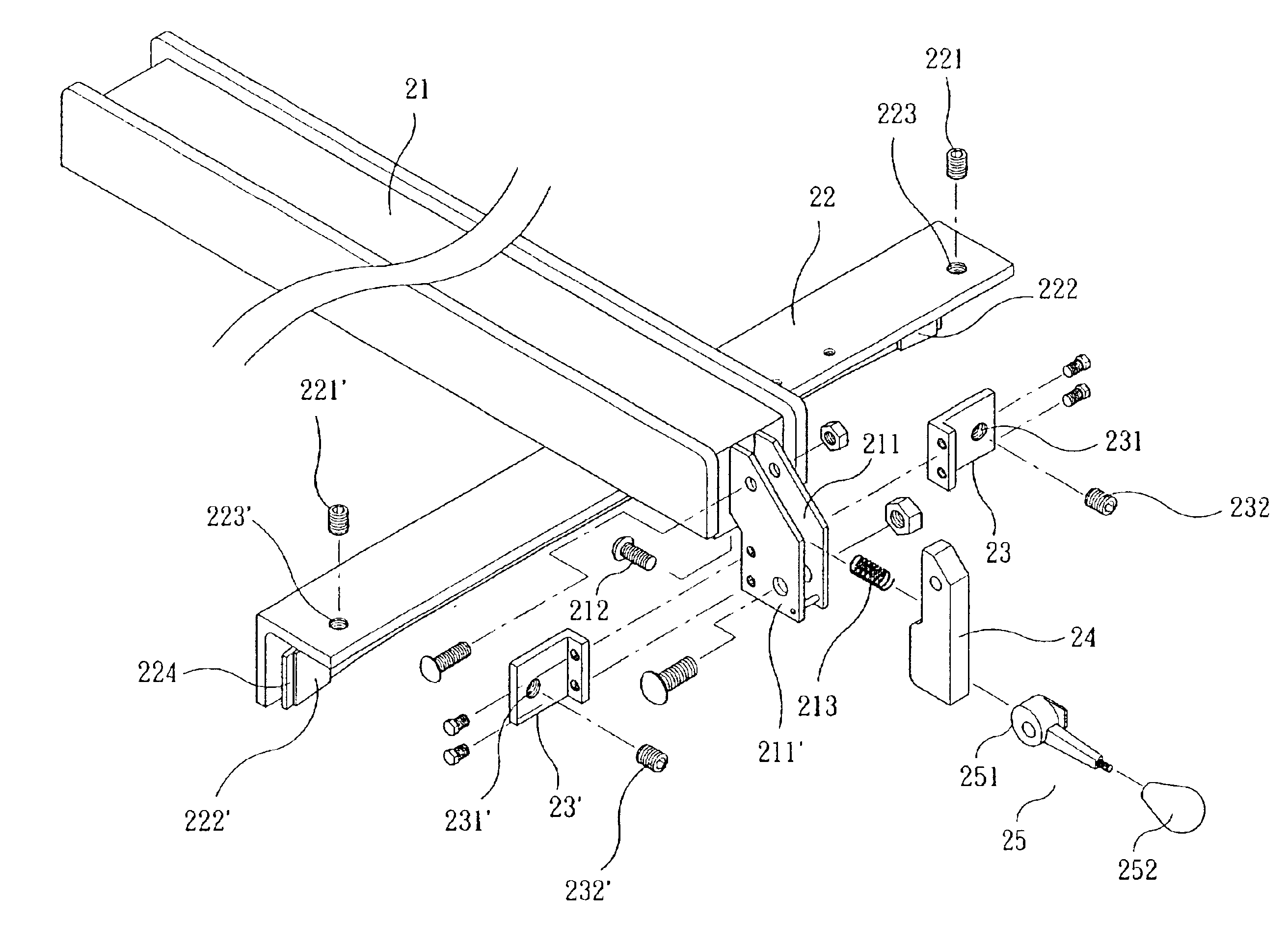
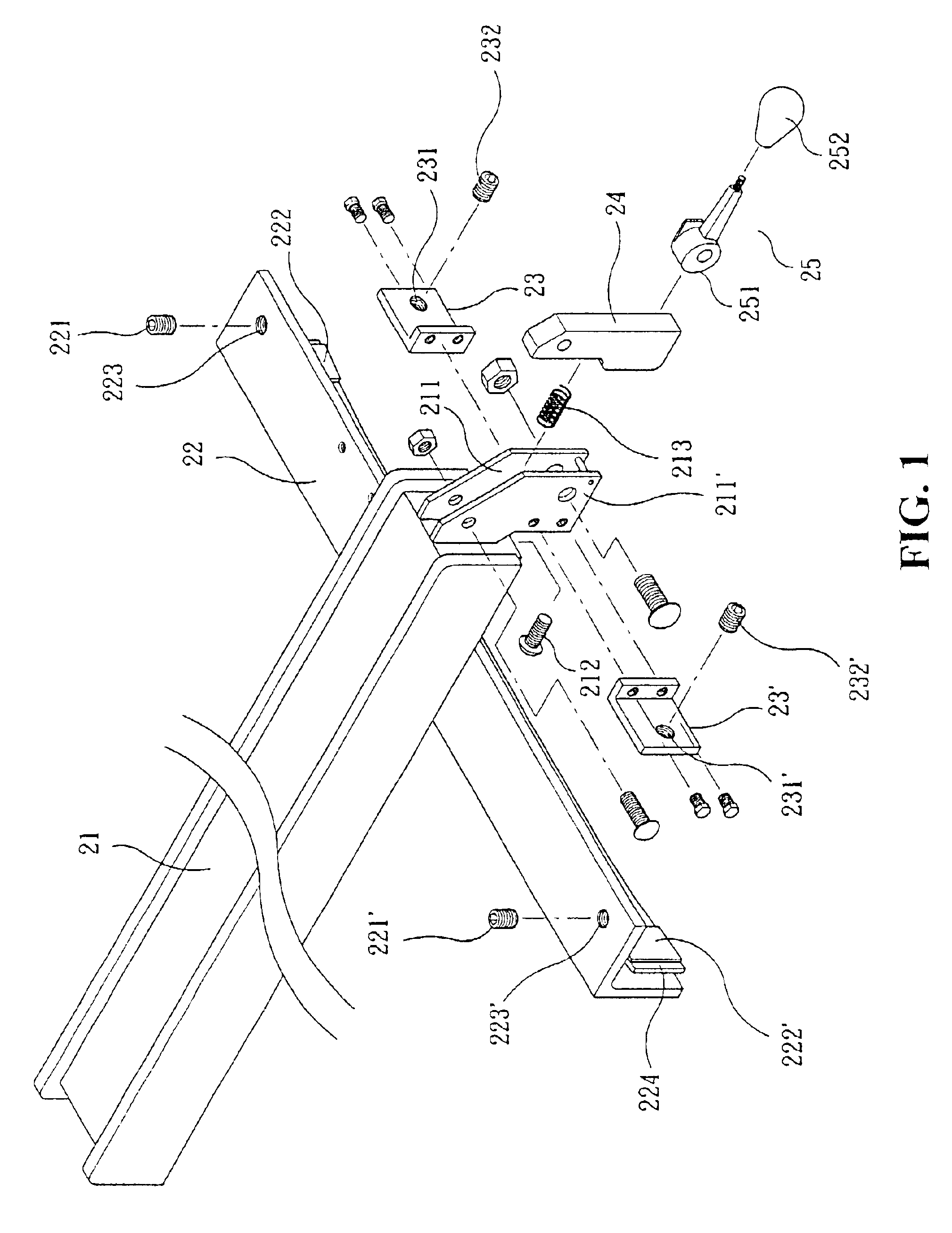
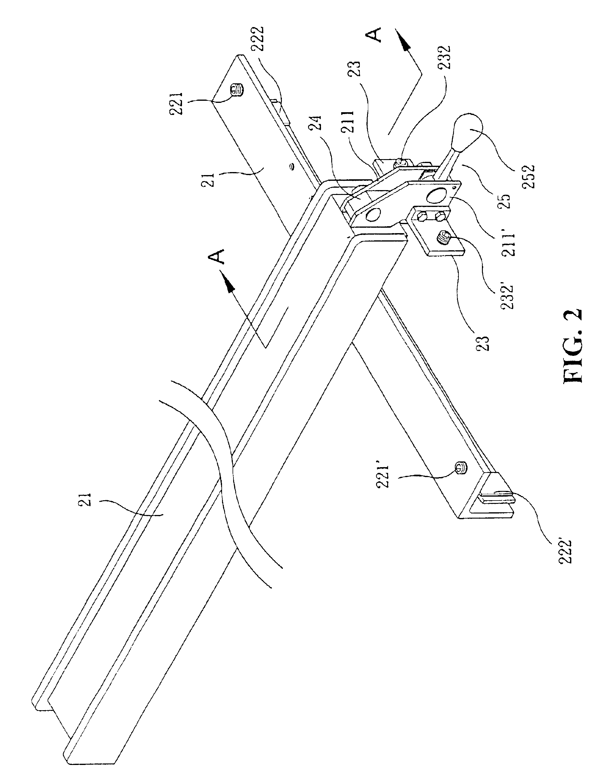
[0020]Referring to FIG. 1, there is shown a positioning rod 21 in accordance with the present invention. The rod 21 is an elongated tubular body and the sides thereof are provided with a resilient plastic board. One end of the bottom face thereof is provided with a plastic frictional plate 214, and the other end of the positioning end (close to the operator end) is provided with a corner board 22 perpendicular to the positioning rod 21. The corner board 22 is mounted to the bottom face of the positioning rod 21 with its horizontal side board, and the two ends of the side board are provided with screw holes 223, 223′. The screw holes 223, 223′ are used for the insertion of plastic screws 221, 221′. The vertical lateral board of the corner board 22 and the lateral side corresponding to a calibration rod 13 is welded to an elongated metal plate 224. The welding point is located at the middle position, and the two ends of the metal plate 224 are bent upward. The two closer ends of the m...


PUM

PropertyMeasurementUnit
distanceaaaaaaaaaa

Abstract

A device for smooth sliding of a positioning rod of a sawing device platform is disclosed. The device includes a support platform or a lateral side of an auxiliary platform with a calibration rod and a gap is formed between the calibration rod. A support platform or the lateral side of the auxiliary platform. The support platform or the auxiliary platform is flatly mounted with the positioning rod which slides between the support platform and the auxiliary platform. A bottom face of one end of the positioning rod, closer to an operator is provided with an inverted L-shaped corner plate perpendicular to the positioning rod, the end face at the same end of the positioning rod is provided with two parallel wing plates having a distance apart, the top section between the two wing plates is pivotally mounted with a swing plate, whereby when the eccentric wheel and the calibration are urged with each other, the screw nuts of the two auxiliary plates dislocate the urging of the calibration rod thereby enabling the positioning rod to be smoothly moved without forming an eccentric movement.

Description

BACKGROUND OF THE INVENTION[0002](a) Technical Field of the Invention[0003]The present invention relates to sawing device platform, and in particular, a device for smooth sliding of a positioning rod of a sawing device platform.[0004](b) Description of the Prior Art[0005]It has been found that the positioning rod of the conventional sawing device platform cannot be moved smoothly along a straight line thereby causing much inconvenience in use.[0006]Therefore, it is an object of the present invention to provide a sawing device platform for smooth sliding of a positioning rod of a sawing device platform.SUMMARY OF THE INVENTION[0007]It is an object of the present invention is to provide a device for smooth sliding of a positioning rod of a sawing device platform, wherein the support platform or the lateral side of the auxiliary platform is provided with a calibration rod and a gap is formed between the calibration rod and the support platform or the lateral side of the auxiliary platf...

Claims


Application Information

Patent Timeline
Patent Type & Authority Patents(United States)
IPC IPC(8): B27B27/02B27B27/10
CPCB27B27/02B27B27/10Y10T83/727Y10T83/7647Y10T83/773Y10T83/858
Inventor YU, SHI-WHI
Owner YU SHI WHI
Learn More