Wayside rail lubrication apparatus and method

a lubrication apparatus and rail technology, applied in the direction of rail lubrication, rail wetting/lubrication, railway components, etc., can solve the problems of rail vehicle wheels suffering wear over time, tread wear, wheel flange wear, etc., and achieve the effect of reducing the quantity of lubricant on the rail section

Inactive Publication Date: 2005-02-15
GENERAL ELECTRIC CO
View PDF32 Cites 20 Cited by
  • Summary
  • Abstract
  • Description
  • Claims
  • Application Information

AI Technical Summary

Benefits of technology

A method of applying lubricant to a rail is further described as including: sensing the presence of a train on a rail; applying a lubricant to a section of the rail in response to the presence of the train after a locomotive at a head of the train has passed the section of rail; and terminating the application of lubricant to the section of rail before an end of the train passes the section of rail so that the quantity of lubricant on the section of rail is reduced by wheels of a plurality of cars proximate the end of the train.

Problems solved by technology

Rail vehicle wheels suffer wear over time due to their contact with the rail.
The treads wear as a result of their contact with the top of the rail, particularly in the event of the wheel slipping with respect to the rail during acceleration or braking events.
The wheel flanges will wear due to their contact with the inside surface of the railhead, particularly on curves and through switches.
In some situations, it is desirable to apply lubrication between the wheel and the flange in order to minimize wear of the flange, while at the same time it is undesirable to apply lubrication to the top of the rail because of the reduction in traction that may be generated against a lubricated rail.
Known wayside lubricating systems often dispense an inappropriate amount of lubrication and / or dispense lubrication when it is not beneficial.

Method used


Image

  • Wayside rail lubrication apparatus and method
  • Wayside rail lubrication apparatus and method

Examples


Embodiment Construction

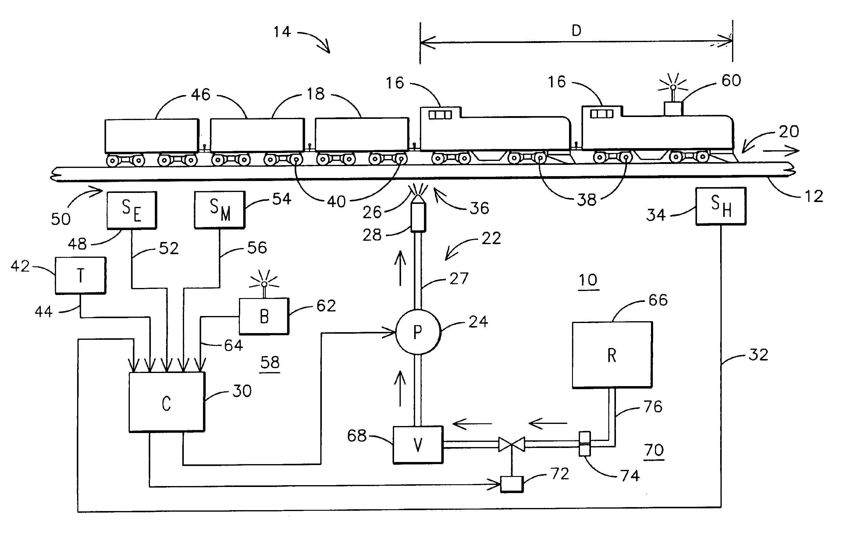
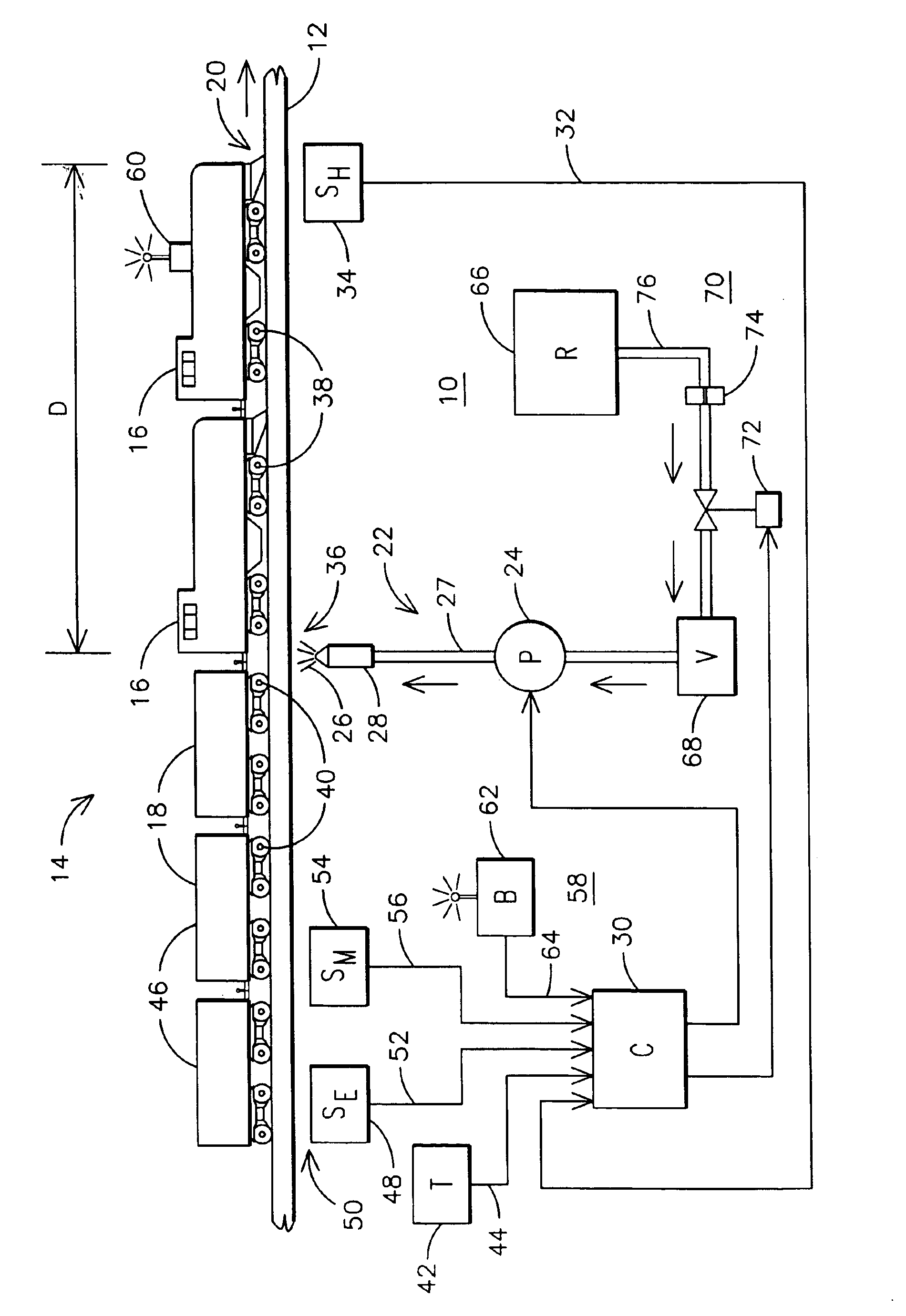
A wayside lubrication apparatus 10 is shown in FIG. 1 as being installed along a rail 12 over which is passing a train 14 having two locomotives 16 and a plurality of load cars 18. The locomotives 16 at the head of the train 14 are located at a first position 20 along the rail 12, for example at the beginning of a curved section of the rail 12.

The wayside lubrication apparatus 10 includes a lubricant dispensing apparatus 22 incorporating a pump 24 for supplying a lubricant 26 to rail 12 through applicator 28. The lubricant 26 may be a petroleum or soybean based oil, a molybdenum or graphite grease or any of the specialty rail lubricants known in the art. The applicator may be a spray nozzle, mechanical wiper, dispenser tube outlet or other known mechanism.

The operation of lubricant dispensing apparatus 22 is controlled by a controller 30, although less sophisticated systems also described herein may not require the control processes utilized in the system shown in the figure. Contro...


PUM


Abstract

A wayside lubrication apparatus (10) for applying a lubricant (26) to a second position (36) of a rail (12) in response to the head of a train (14) being proximate a first position (20) of the rail. The distance (D) between the two positions prevents the lubricant from reducing the traction capability of the drive wheels (38) of the locomotives (16). The application of the lubricant is terminated before a number of rear load cars (46) passes the lubricant applicator (28) so that the residual lubricant remaining on the rail after the train has passed is reduced. Operation of the lubricant dispensing apparatus (22) may be bypassed by an operator-controlled bypass device (60) or in response to a signal (56) indicating moisture on the rail. To avoid excessive lubricant on the rail, a timer (42) is used to prevent repeated applications of lubricant within a predetermined time period, and/or a lubricant container (68) is refilled at a controlled rate to proportion the amount of lubricant applied in response to a second consecutive train.

Description

FIELD OF THE INVENTIONThis invention relates generally to the field of rail transportation, and more particularly to the field of rail lubrication systems, and specifically to a wayside rail lubrication apparatus and method.BACKGROUND OF THE INVENTIONA typical train includes one or more locomotives pulling a plurality of load cars. Each vehicle in the train includes a plurality of metal wheels that roll along the metal rail as the train is propelled along the track. The rolling contact between the wheel and the rail provides an efficient mode of transportation, particularly for heavy loads. Proper interaction between the wheel and the rail is critical for safe, reliable, efficient operation of the train.A rail includes a bottom mounting flange, a top railhead that makes contact with the vehicle wheel, and a flange interconnecting the flange and the railhead. A vehicle wheel includes a center hub mounted onto the vehicle axle, a plate extending outwardly from the hub, and an outer ri...

Claims


Application Information

Patent Timeline
Patent Type & Authority Patents(United States)
IPC IPC(8): B61K3/00
CPCB61K3/00
Inventor KUMAR, AJITH KUTTANNAIRWORDEN, BRET DWAYNE
Owner GENERAL ELECTRIC CO
Why Eureka
Try Eureka