Vehicle handle assembly

a technology for vehicle handles and components, applied in anti-theft devices, lock applications, instruments, etc., can solve the problems of inability to implement, electrical components heretofore have been bulky and expensive, and electrical components have been somewhat limited in their us

Inactive Publication Date: 2005-02-15
DONNELLY CORP
View PDF23 Cites 121 Cited by
  • Summary
  • Abstract
  • Description
  • Claims
  • Application Information

AI Technical Summary

Benefits of technology

In one aspect, the flexible carrier member is mounted to the handle portion. For example, the flexible carrier member may be mounted to the handle portion by an adhesive. In addition, the handle portion includes a recessed portion in which the carrier member is positioned. Preferably, t...

Problems solved by technology

While it is known to have electrical components associated with some styles of handles, these electrical components heretofore have been bulky and expensive.
As a result, these electrical components have been some what l...

Method used


Image

  • Vehicle handle assembly
  • Vehicle handle assembly
  • Vehicle handle assembly

Examples


Embodiment Construction

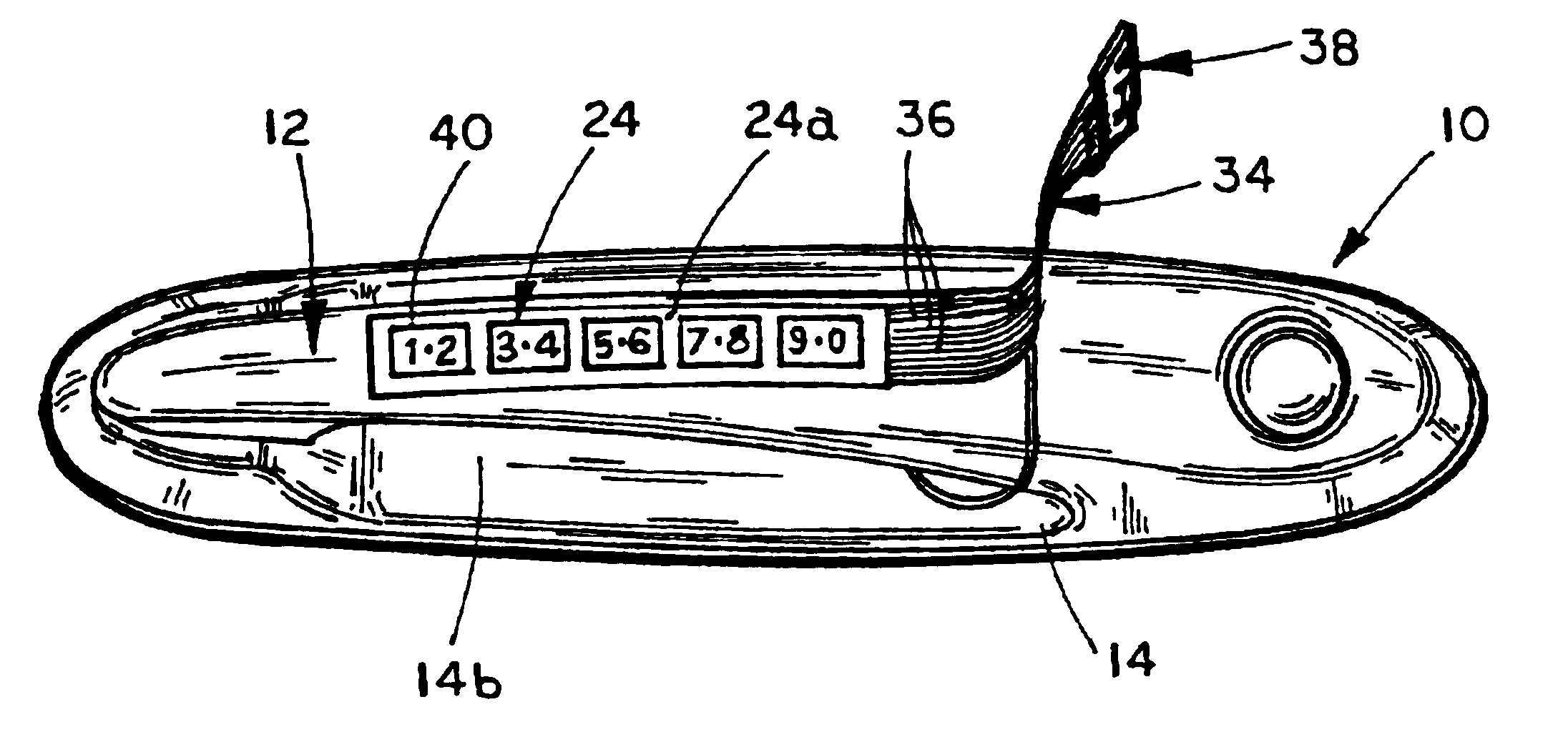
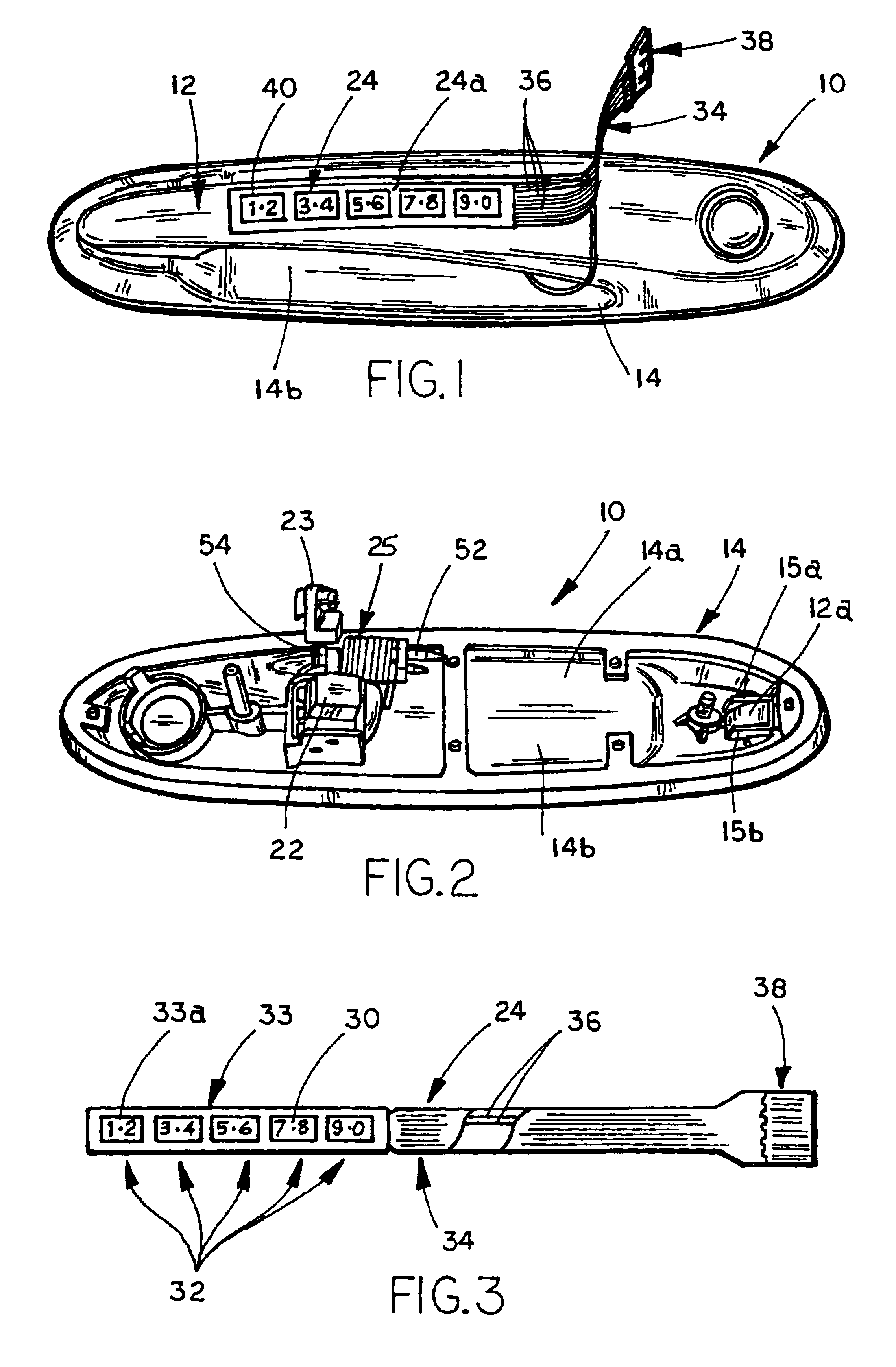
The numeral 10 generally designates a handle assembly of the present invention. As will be more fully described below, handle assembly 10 is adapted to be mounted to a vehicle, such as a side door of the vehicle, and incorporates electrical components that lock or unlock the latching mechanism associated with the handle assembly all in a manner heretofore unknown.

Handle assembly 10 includes a fixed portion 14 and a movable portion 12, which is movably mounted to the fixed portion, and in adapted to move between a home or un-actuated position (as shown in FIG. 5) and a pivoted or actuating position (as shown generally in phantom in FIG. 5). The illustrated embodiment, movable portion 12 comprises a strap or strap-type handle or handle portion 12, and fixed portion 14 comprises a base. Handle portion 12 is pivotal base 14 about a vertical axis 20 on one end of handle portion 12 which causes the second end of handle portion 12 to lift away from base and the body of the vehicle when pul...


PUM


Abstract

A handle assembly for a vehicle includes a base, which is adapted to mount to a vehicle, and a handle portion, which is movably mounted to the base. The handle portion is adapted to connect to a vehicle latching mechanism. The handle assembly includes at least one switch mounted to the handle portion and an electrical circuit, which is adapted to connect to a locking control system for the vehicle latching mechanism. The switch is adapted to open and close the electrical circuit to generate electrical signals to the locking control system to unlock the vehicle latching mechanism.

Description

BACKGROUND OF THE INVENTIONThe present invention relates to door handle assemblies and, more particularly, to door handle assemblies for vehicles.Until recently, door handle assemblies for vehicles have been purely mechanical devices, requiring a handle portion, which is coupled to a latching mechanism, to be rotated or pivoted to either latch or unlatch the latching mechanism. In addition, a key has been typically required to lock or unlock the latching mechanism. For example, some door handle assemblies include a strap type handle, which pivots about one end of the handle. The pivoting end of the handle is coupled to a latch mechanism, for example by a cable or a linkage, which is actuated by the pivoting of the handle. Other door handle assemblies include a paddle type handle, which is mounted to a pivotal shaft, for example, in a recessed portion of the door, with the shaft being coupled to the latch mechanism, which is actuated by the pivoting of the shaft. Other styles include...

Claims


Application Information

Patent Timeline
IPC IPC(8): B60Q1/26E05B65/20E05B17/00E05B17/10
CPCB60Q1/2669E05B81/76E05B17/10G07C9/0069E05B81/77E05B85/16Y10T70/7068Y10T70/5898
Inventor HUIZENGA, DAVID J.
Owner DONNELLY CORP
Why Eureka
Try Eureka