Gel hydration system

Active Publication Date: 2005-02-15
HALLIBURTON ENERGY SERVICES INC
View PDF14 Cites 24 Cited by
  • Summary
  • Abstract
  • Description
  • Claims
  • Application Information

AI Technical Summary

Benefits of technology

The flow conduits of the present invention are preferably perforated such that each flow conduit has a plurality of ports or openings in a vertical portion thereof through which incoming gel will pass. Thus, incoming gel will flow out of flow conduits through the ports or openings in the sides thereof and through an exit end of the flow conduit. The ports in the flow conduits are oriented so as to create multi-directional flow of incoming gel into the hydration tank and thu

Problems solved by technology

With prior art hydration tanks, incoming gel has a tendency to finger through existing gel and exit t

Method used


Image

  • Gel hydration system
  • Gel hydration system
  • Gel hydration system

Examples


Example

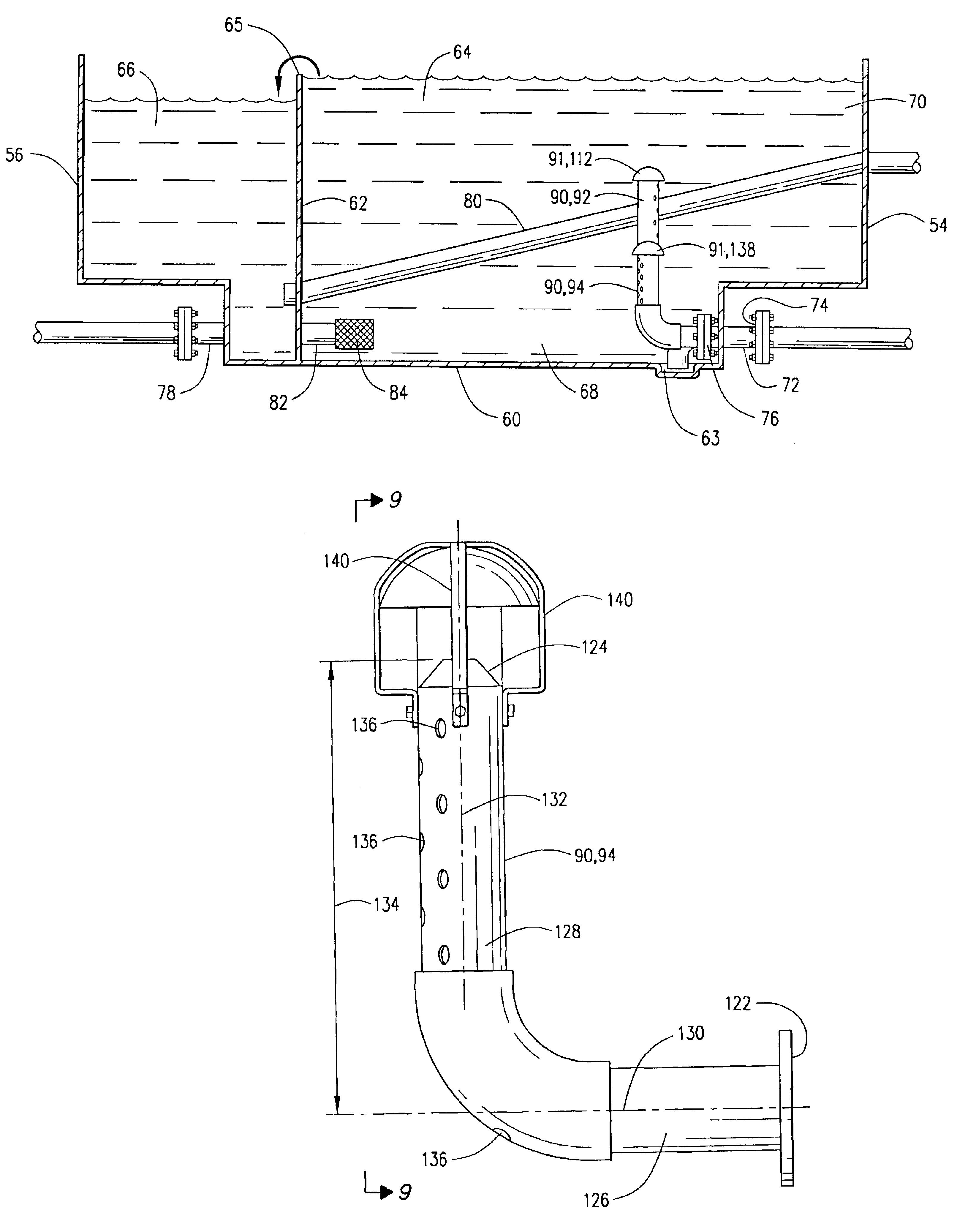
Hydration tank 50, including the hydration apparatus or hydration system 52 of the present invention is shown in FIGS. 4-11. Hydration tank 50 has an inflow or forward end 54, an outflow or rear end 56, a top 58, a bottom 60, and sides 61. Bottom 60 may include a cup or depression 63 therein. A weir plate 62 divides the hydration tank 50 into an inflow portion 64 and an outflow portion 66. Gel in the hydration tank 50 will roll over an upper end 65 of weir plate 62. As is apparent from the drawings, hydration tank 50 is preferably a T-tank 50 having a bottom portion 68 and an upper or top portion 70. Hydration tank 50 includes a plurality of gel inlets 72 having an entrance 74 and an exit 76. Gel is communicated into hydration tank 50 from a pre-blender (not shown) through gel inlets 72. Hydration tank 50 likewise includes the drain conduit 32, and includes a plurality of gel outlets 78. Lower end 33 of drain conduit 32 is positioned over, and may extend into, depression or cup 63 f...


PUM

PropertyMeasurementUnit
Timeaaaaaaaaaa
Dispersion potentialaaaaaaaaaa
Flow rateaaaaaaaaaa

Abstract

A hydration apparatus for use with a hydration tank. The hydration apparatus disperses incoming gel into existing gel in the hydration tank to increase the hydration time of the incoming gel. The hydration apparatus includes flow conduits communicated with gel inlets in the hydration tank. The flow conduits redirect the flow of the incoming gel. The flow conduits preferably redirect the flow from a generally horizontal direction to generally vertically upwardly direction. The hydration apparatus has a plurality of deflectors positioned in the hydration tank. Flow exiting an end of the flow conduits is deflected by the deflectors and dispersed into existing gel in the hydration tank. The flow conduits are preferably perforated flow conduits so that a portion of incoming gel passes through openings in the sides of the flow conduits while a portion of the incoming gel passes through an exit of the flow conduits. Incoming gel is therefore sufficiently dispersed into existing gel to increase the hydration time of incoming gel.

Description

BACKGROUND OF THE INVENTIONThe present invention relates to a method and apparatus for hydrating a gel, and more specifically to improved methods and apparatus for hydrating a fracturing gel, or fracturing fluid in a hydration tank.Producing subterranean formations penetrated by wellbores are often treated to increase the permeabilities of conductivities thereof. One such production stimulation involves fracturing the subterranean formation utilizing a viscous treating fluid. That is, the subterranean formation or producing zone is hydraulically fractured whereby one or more cracks or fractures are created therein.Hydraulic fracturing is typically accomplished by injecting a viscous fracturing fluid, which may have a proppant such as sand or other particulate material suspended therein, into the subterranean formation or zone at a rate and pressure sufficient to cause the creation of one or more fractures in the desired zone or formation. The fracturing fluid must have a sufficientl...

Claims


Application Information

Patent Timeline
IPC IPC(8): B01F3/08B01F15/02B01F5/02
CPCB01F3/0861B01F15/0203B01F5/0206Y10T137/206B01F23/45B01F25/21B01F35/712
Inventor GRAHAM, SR., JAYCE L.
Owner HALLIBURTON ENERGY SERVICES INC
Why Eureka
Try Eureka