Cold trap to increase gas residence time to increase condensation of vapor molecules

Inactive Publication Date: 2009-10-08
HARVARD BIOSCIENCE INC
View PDF5 Cites 5 Cited by
  • Summary
  • Abstract
  • Description
  • Claims
  • Application Information

AI Technical Summary

Benefits of technology

[0012]The present invention provides partitions or surfaces (used interchangeably herein) added to the inner chamber of a closed cold trap container. The partitions or surfaces create a lengthened path from inlet to outlet within the closed container. This increases the residence time o

Problems solved by technology

Habitual use of a fume hood to dispose of solvent vapors has become irresponsible.
This results in poor yields of condensed vapor molecules due to the fast moving gas residing for too little time in the typical cold trap.
Such systems are impract

Method used


Image

  • Cold trap to increase gas residence time to increase condensation of vapor molecules
  • Cold trap to increase gas residence time to increase condensation of vapor molecules
  • Cold trap to increase gas residence time to increase condensation of vapor molecules

Examples


Example

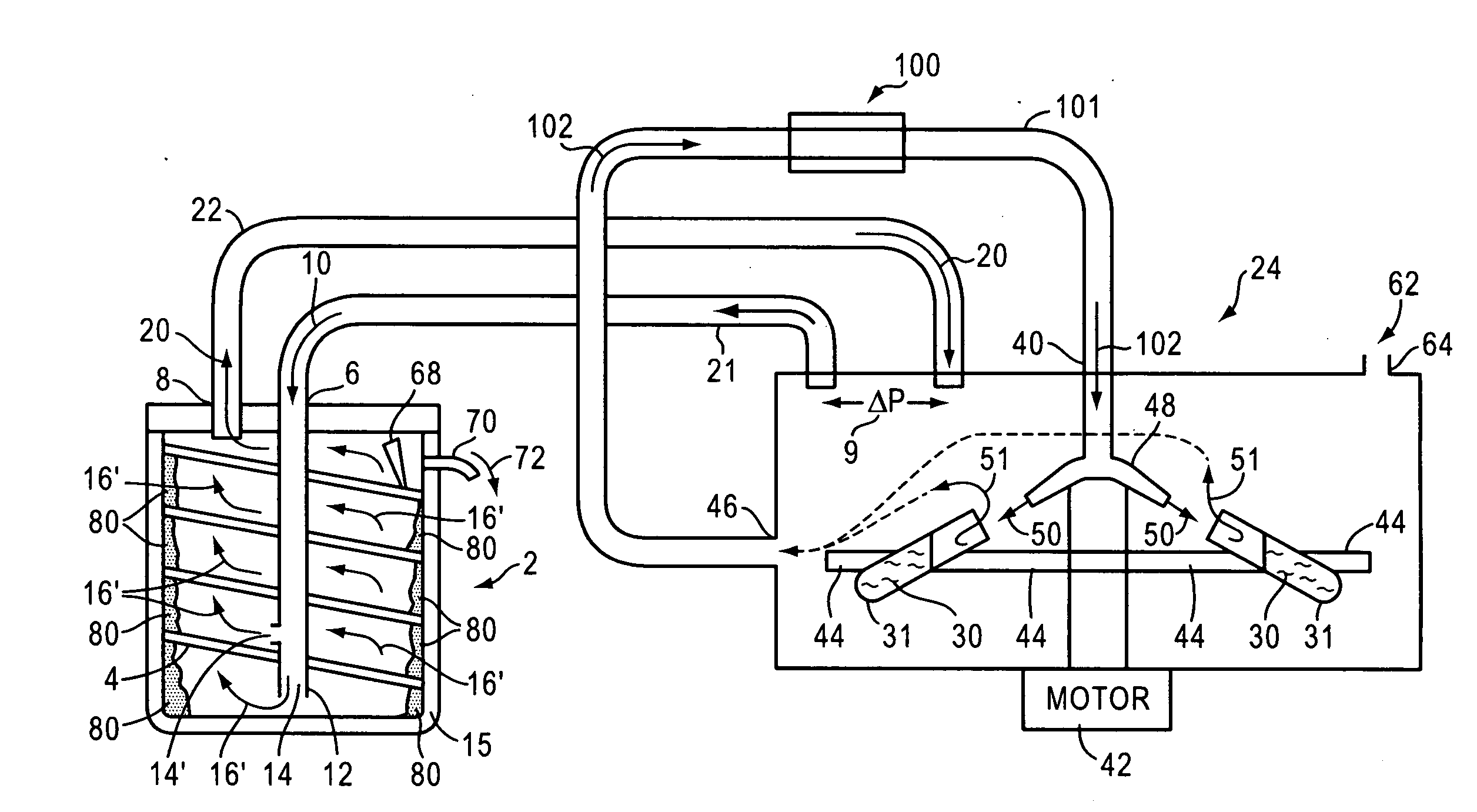
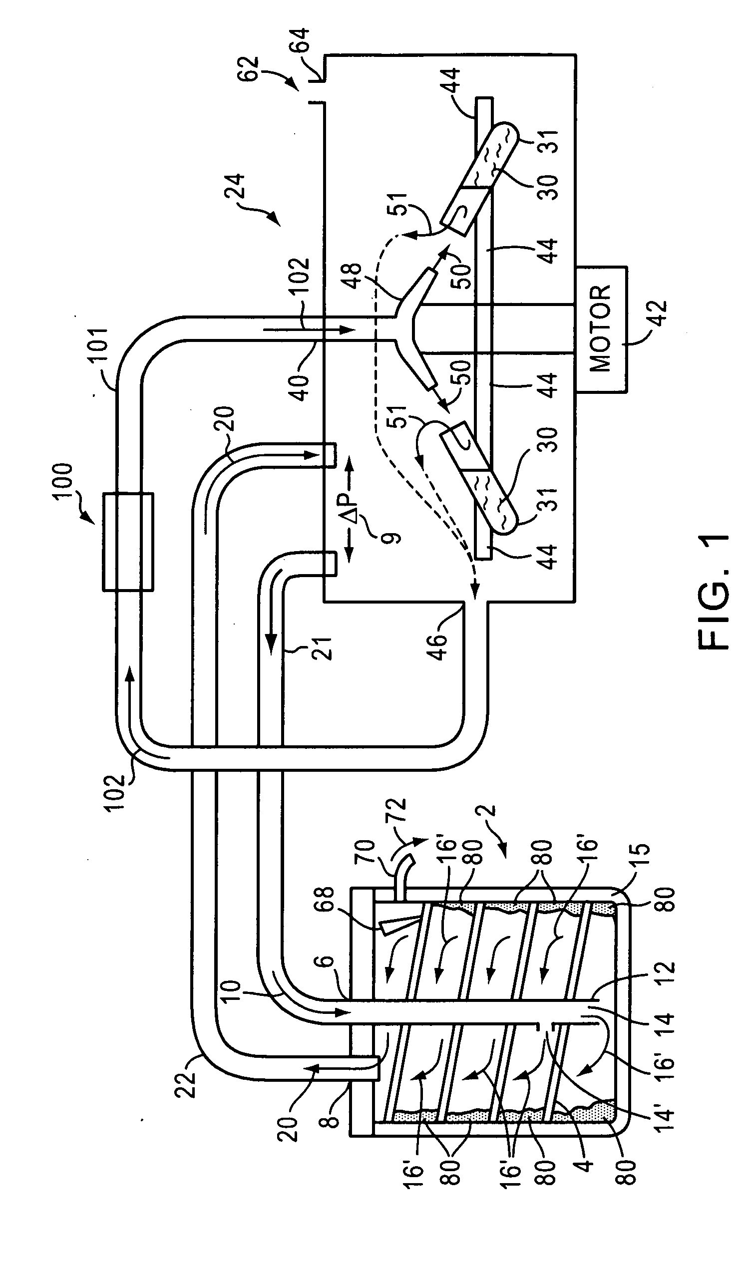
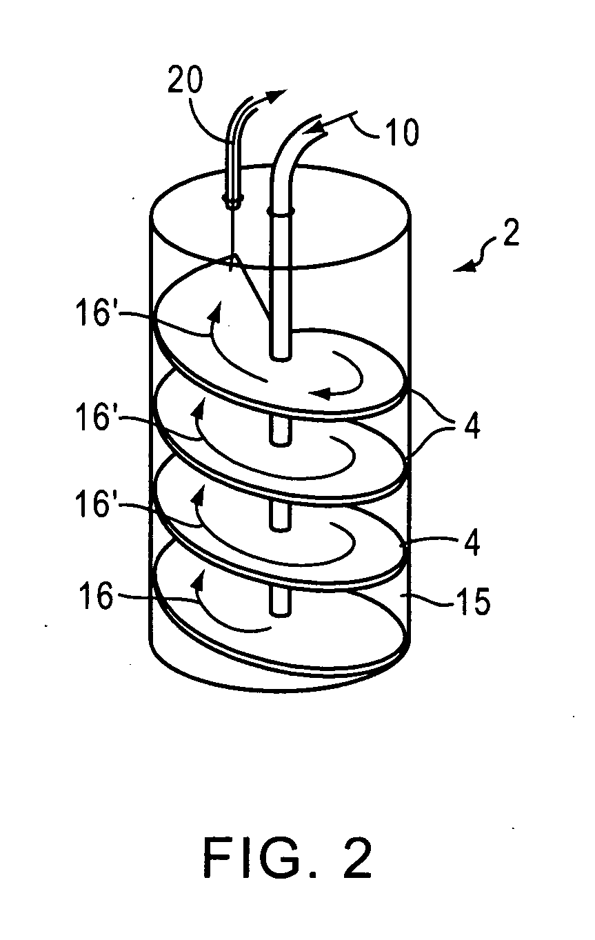
[0022]FIG. 1 includes a cold trap 2 with a vertical tube 12 leading to a bottom exit 14. Incoming flowing wet vapor 10 circulate 16′ up the spiral inclined plane 4 forming a path to an outlet 8. The gas flows 16′ from the opening 14 and hits the inner wall of the container 15 where it condensers 80. The wet vapor follows the spiral path 4 around the center tube 12 tracing a path (the 16's) to the outlet 8. The dry exiting gas flows 20 via the tube 22 back to the source 24 of the wet vapor. The outside of the container 15 is cooled and the solvent molecules in the wet vapor condense and solidify 80 along the inner side of the container 15. There may be other exits from the center above the lowest exit 14. These other exits may be smaller allowing less vapor to exit the center tube, but they allow the cold trap to operate when the exit 14 is effectively plugged by the condensed material 80.

[0023]The spiral inclined plane 4 is made to abut the inner surface of the container 15, and the...


PUM

PropertyMeasurementUnit
Thermal conductivityaaaaaaaaaa
Residence timeaaaaaaaaaa

Abstract

A cold trap is disclosed with a chamber having partitions or surfaces that direct the incoming wet vapor to substantially all of the cold inner surfaces of the cold trap. Typically, the cold inner surfaces are the inner walls of the chamber. The interaction of the wet vapor and the cold surfaces condense the molecules. The wet vapor minus the condensed molecules may be heated and returned to the source of the wet vapor for reuse. One example of the partitions or surfaces is a spiral inclined plane where the wet vapor flows along the spiral plane that acts to drive the wet vapor toward the cold inner walls of the chamber.

Description

CROSS REFERENCE TO RELATED APPLICATIONS[0001]The present application is related to a provisional patent application filed Apr. 4, 2008, Ser. No. 61 / 042,456 entitled: “Design of Cold Trap to Increase Residence Time to Increase Condensation of Vapor Molecules,” and is of common ownership and inventorship. This provisional application is hereby incorporated herein by reference.BACKGROUND OF THE INVENTION[0002]1. Field of the Invention[0003]The present invention relates to removing vapor molecules from a gas, usually carbon dioxide or nitrogen, and more particularly to circulating the gas through a cold trap where the vapor molecules condense.[0004]2. Background Information[0005]Sample concentrators are prevalent in virtually all liquid processing operations. Materials of interest are typically synthesized, modified, and purified in solution-based process steps. To recover these dissolved non-volatile materials as dry powders and / or to increase the concentration of compounds; vacuum cen...

Claims


Application Information

Patent Timeline
IPC IPC(8): B01D8/00
CPCB01D5/0003B01D5/0006B01D2257/504B01D53/002B01D2256/10B01D5/0078Y02P70/10
Inventor HEDBERG, HERBERT J.
Owner HARVARD BIOSCIENCE INC
Why Eureka
Try Eureka