Apparatus for establishing adjustable depth bed in trenches for utility lines and encasing the lines

a technology of adjustable depth bed and utility line, which is applied in the direction of pipe/joint/fitting, pipe laying and repair, construction, etc., can solve the problems of affecting the installation of utility or utility, and often not being able to guarantee the predetermined depth of select material, etc., to achieve the effect of high versatility and simplified supply of material

Active Publication Date: 2005-02-15
TRENCHING
View PDF10 Cites 15 Cited by
  • Summary
  • Abstract
  • Description
  • Claims
  • Application Information

AI Technical Summary

Benefits of technology

The unit of the invention is relatively simple, yet highly versatile in being able to separately adjust the depth of each of the bed and the encas

Problems solved by technology

There are drawbacks to this type of unit.
The material as it gravitates on and around the utility or utilities being installed produces a vertical shear force on and can potentially damage the utility or utilities as they leave the control of the guide device which is above the bottom of the trench.
This predetermined depth of select material can frequently not be guaranteed since most types of select material have varying flow and adhesive characteristics that change greatly with differing moisture contents.
Obtaining the desired amount of select material required under the utility or utilities being installed is also made increasingly difficult as the diameter of the utilities become larger since this requires the select mat

Method used


Image

  • Apparatus for establishing adjustable depth bed in trenches for utility lines and encasing the lines
  • Apparatus for establishing adjustable depth bed in trenches for utility lines and encasing the lines
  • Apparatus for establishing adjustable depth bed in trenches for utility lines and encasing the lines

Examples


Embodiment Construction

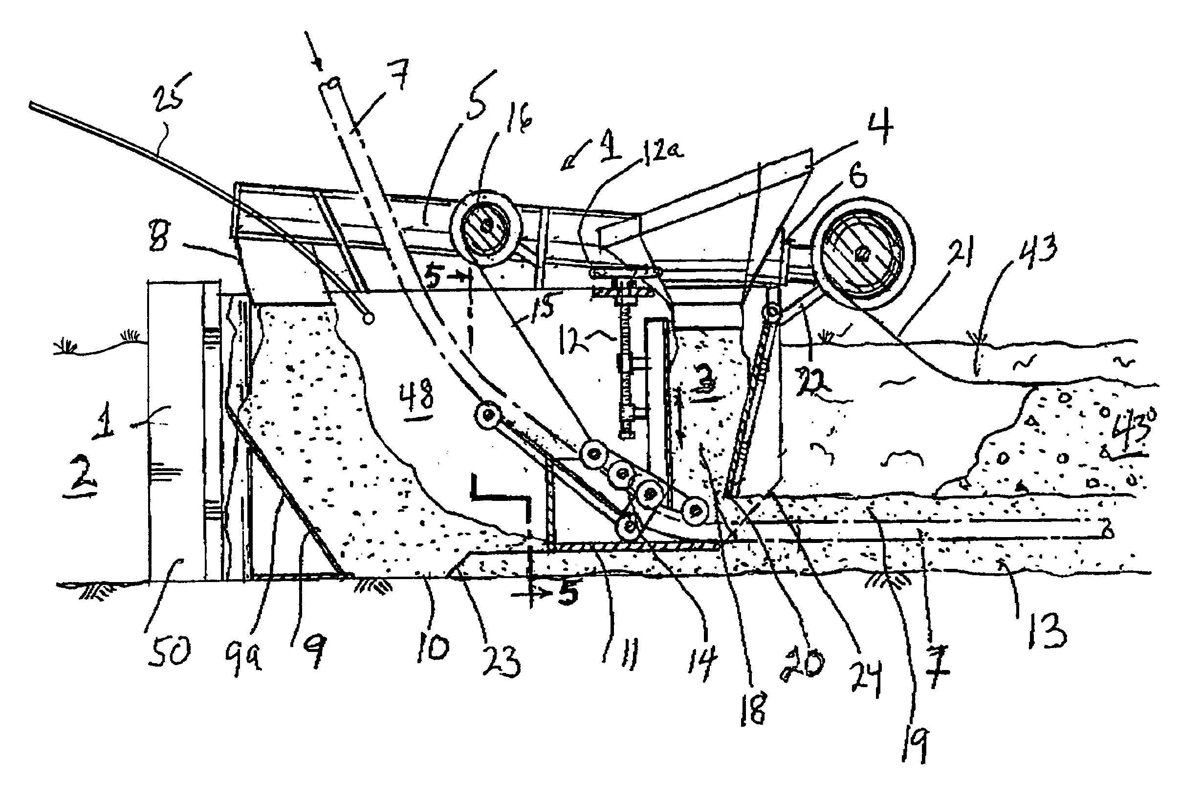
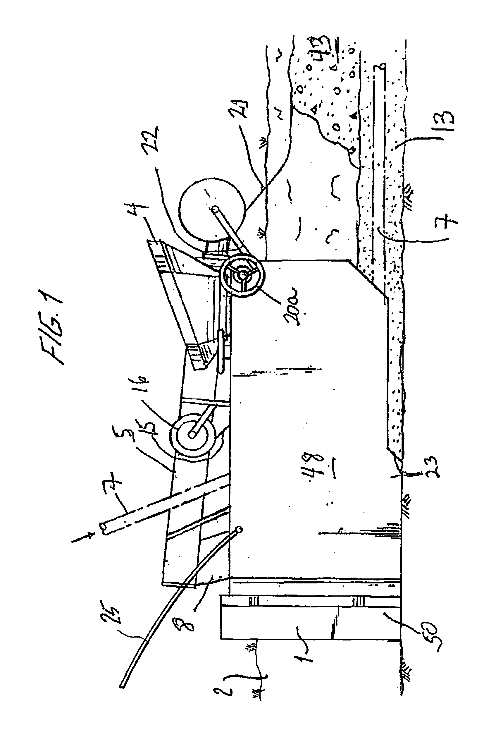
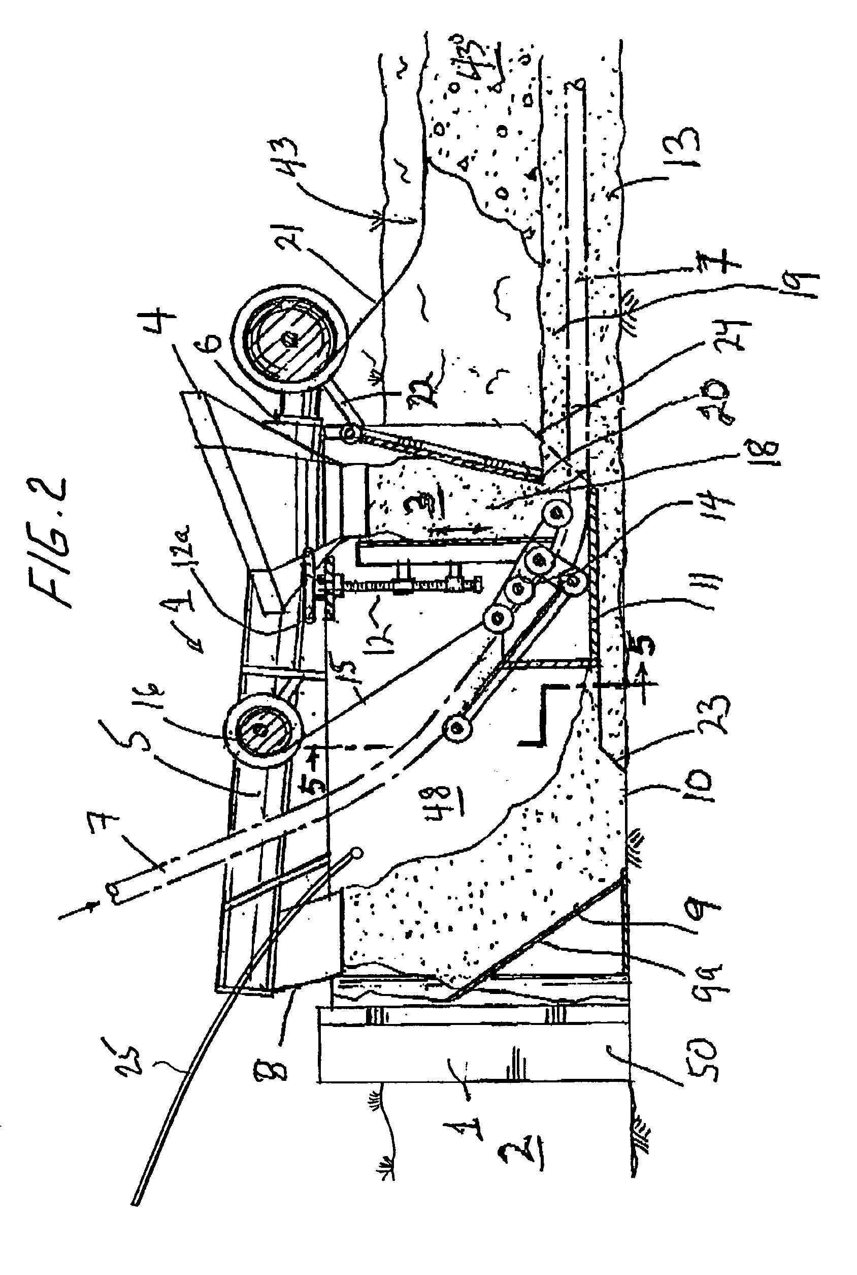
Referring to FIGS. 1 and 2, the mechanized unit 1 of the invention is pulled through an existing trench 2, usually dug by a trenching unit (not shown) of any conventional type, or by any other mechanical means. For example, the unit 1 can be mounted on the same frame as the trenching unit that digs the trench 2. The combined trenching unit and the mechanized unit 1 can have its own motive means or be pulled or pushed along by any suitable motive means. Alternatively, the trenching unit and the unit 1 of the invention can be separate from each other and each moved by its own motive means. The mechanized unit 1 is moved forward in the trench 2 (right to left in FIGS. 1 and 2).

The unit 1 has a frame 50 on which a hopper 4 is mounted. Select material 3 is loaded into the top inlet of hopper 4 by any mechanical means such as a mobile material handling unit, ready mix truck, front end loader or any other suitable piece of equipment. The material can be sand, concrete, soil, mixtures of ma...


PUM


Abstract

A mechanized unit that places a predetermined and adjustable depth of a selected bedding material on the bottom of a trench in the ground, then places on the bed a continuous length of a utility or utilities having a predetermined spatial relationship with each other and then encases the utility or utilities with additional select material to a predetermined and adjustable depth of cover in a continuous operation. The unit has a single hopper that receives and contains the material that is used both to form the bed and also to encase the one or more utilities laid on the bed. The hopper conveys material in the direction of movement of the unit and the material is dispensed from the conveyor into the trench to form the bed. An adjustable height blade is provided which both sets the bed height and also smoothes the bed upper surface. As the unit moves, the utility or utilities are laid on the bed upper surface. Thereafter, material is dispensed from the bottom of the hopper on top of and around the utility or utilities to encase them. An adjustable height blade is also provided to set the height of the encasement and also to smooth out its upper surface.

Description

FIELD OF THE INVENTIONA mechanized unit for laying a bed of a material in a trench on which a utility is placed and then for encasing the utility in the material.BACKGROUND OF THE INVENTIONMechanized units are known that are moved through an existing trench in the ground for the purpose of laying a continuous length or lengths of a utility or utilities, such as conduits, pipes, cables, etc., or combinations thereof.One type of mechanized unit exists for installing a utility surrounded by a select material at a predetermined position within an encasement of the select material in a trench. Where there is more than one utility line, the unit maintains a predetermined spatial relationship of the utilities with each other. Such a mechanized unit is propelled along the trench in which the flexible utility or utilities are being installed. The utility or utilities passes down through the unit by means of a guide device that supports the utility or utilities at a predetermined height above...

Claims


Application Information

Patent Timeline
IPC IPC(8): E02F5/12E02F5/14E02F5/02F16L1/028
CPCE02F5/12F16L1/028E02F5/14
Inventor LOPATA, MICHAEL E.
Owner TRENCHING
Why Eureka
Try Eureka