Automatic locking depth guide for cutting tools and the like

a technology of automatic locking and depth guides, which is applied in the direction of manufacturing tools, portable power tools, metal-working machine components, etc., can solve the problems of reducing the ability of the operator to control precisely the cut, affecting the accuracy of the use of the tool, and affecting the accuracy of the tool

Inactive Publication Date: 2005-02-15
CREDO TECH CORP
View PDF32 Cites 30 Cited by
  • Summary
  • Abstract
  • Description
  • Claims
  • Application Information

AI Technical Summary

Problems solved by technology

With extended and continuous operation, the motor housing of a cutting tool can become warm, and cutting tool vibrations may cause an operator's hands and arms to become fatigued.
Extended and continuous use of a Spiral Saw™ cutting tool by grasping the motor housing can, therefore, become uncomfortable, reducing the ability of the operator to control precisely the cut being made.
The handle may be removed from the tool, for example, when the Spiral Saw™ cutting tool is to be used in tight quarters wherein the handle might become an obstacle to precise control of the cutting tool.
The accumulated debris can obscure the point of the cut, i.e., the point where a cutting bit enters a work piece, thereby interfering with accurate use of the tool.

Method used


Image

  • Automatic locking depth guide for cutting tools and the like
  • Automatic locking depth guide for cutting tools and the like
  • Automatic locking depth guide for cutting tools and the like

Examples


first embodiment

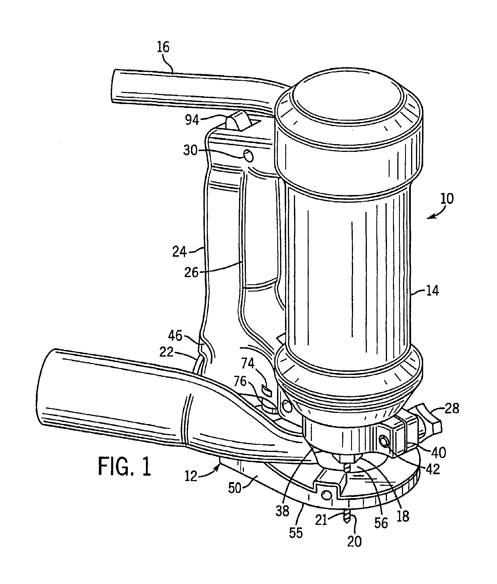
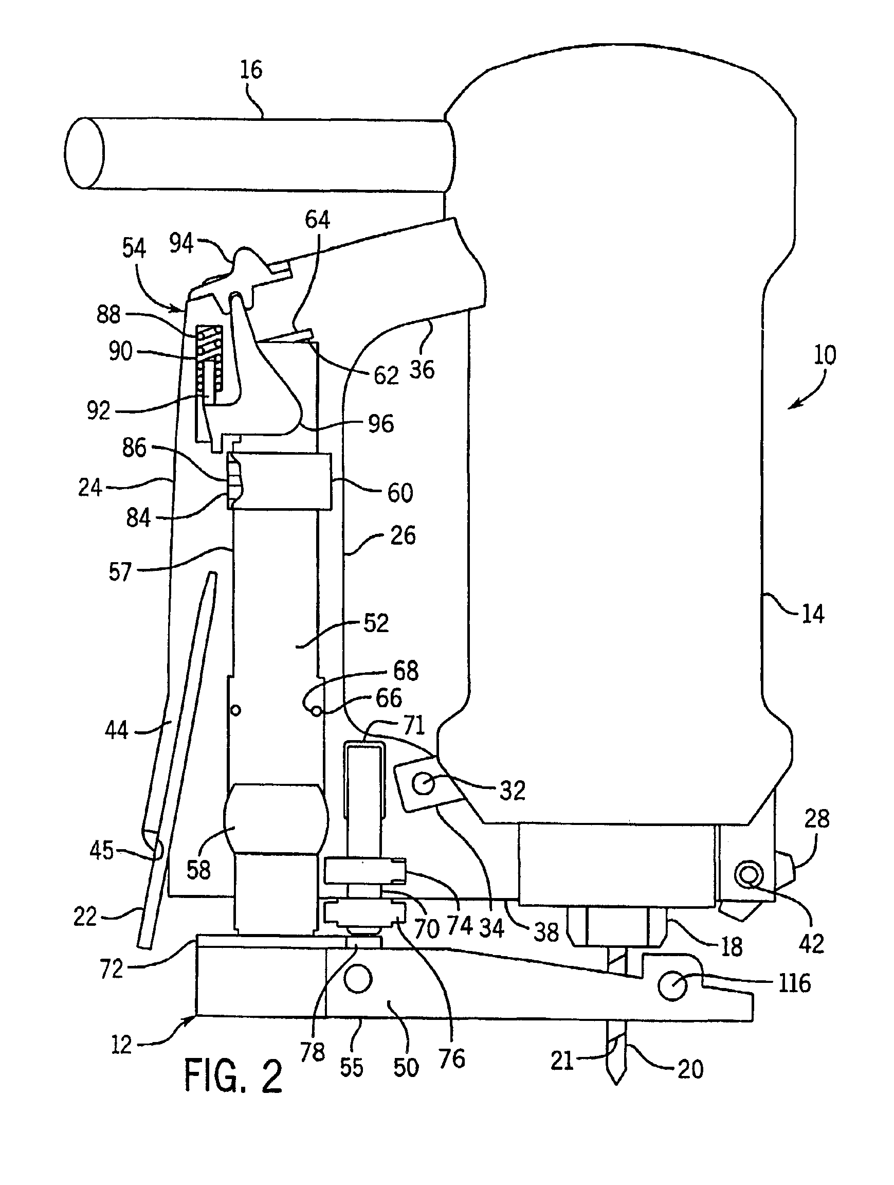
the automatic locking depth guide 12 in accordance with the present invention will now be described in further detail with reference to FIGS. 1 through 5. Automatic locking depth guide 12 includes a depth guide base 50, a depth guide shaft 52 attached to the base 50, and an automatic locking and release mechanism 54 coupled to the shaft 52.

Depth guide base 50 is preferably made of a strong, rigid material, for example, machined from a piece of steel or aluminum. Alternatively, depth guide base 50 may be formed from a polymeric material such as polyethylene or polypropylene. Depth guide base 50 includes a substantially flat bottom surface 55. In use, the bottom surface 55 of the depth guide base 50 is positioned against a work piece being cut as cutting tool 10 is moved along the work piece. Therefore, bottom surface 55 of depth guide base 50 is preferably smooth, such that bottom surface 55 of depth guide base 50 and, therefore, tool 10 attached thereto, slides easily across a work ...


PUM

PropertyMeasurementUnit
depthaaaaaaaaaa
frictionaaaaaaaaaa
heightaaaaaaaaaa

Abstract

A guide (12) for setting the depth of cut of a rotary cutting tool, or other hand-held power tool, which automatically locks into a desired position to set the depth of a cut without requiring manual operation of a locking knob or similar structure. The depth guide is released from the locked position by actuation of a release switch (94). The depth guide includes a depth guide base (50), a depth guide shaft (52) attached to the depth guide base, and an automatic locking and release mechanism (54) coupled to the depth guide shaft. The automatic locking and release mechanism and depth guide shaft may be mounted in a handle (24) of the hand-held power tool, such as a detachable handle, for mounting the depth guide to the tool.

Description

FIELD OF THE INVENTIONThis invention pertains generally to hand-held power tools, such as hand-held cutting tools. Specifically, the invention pertains to adjustable depth guides for setting the depth of cut to be made by such power tools.BACKGROUND OF THE INVENTIONA Spiral Saw™ cutting tool is a hand-held power tool having an electric motor that rotates a cutting tool bit at high speeds. Such a cutting tool bit includes a sharp cutting edge that is wrapped in a helix around the axis of the bit. The cutting tool bit is designed for cutting perpendicular to the axis of the bit. The electric motor that drives the bit is enclosed in a motor housing which is generally cylindrical in shape, with the cutting tool bit extending from one end of the motor housing along the axis of the housing. A Spiral Saw™ cutting tool is used to remove material from a work piece by moving the rotating cutting tool bit through the work piece in a direction perpendicular to the axis of rotation of the bit. A...

Claims


Application Information

Patent Timeline
Patent Type & Authority Patents(United States)
IPC IPC(8): B25F5/00B25F5/02B27C5/00B27C5/10
CPCB25F5/003B25F5/029B27C5/10Y10T408/99Y10T409/306608Y10T409/308624Y10T409/30868Y10T409/304088Y10T409/308176Y10T409/307952Y10T409/306496Y10T408/5653
Inventor KOPRAS, ROBERT K.ADLER, SCOTTKOPRAS, JASON R.STANLEY, JAMES
Owner CREDO TECH CORP
Why Eureka
Try Eureka