
Passive safety device for needle of IV infusion or blood collection set

a safety device and needle technology, applied in the field of passively activated safety shields for needles, can solve the problems of difficult access and release of latches, transmission of diseases, needle sticks,

Inactive Publication Date: 2005-02-15
BECTON DICKINSON & CO
View PDF35 Cites 57 Cited by
  • Summary
  • Abstract
  • Description
  • Claims
  • Application Information

AI Technical Summary

Benefits of technology

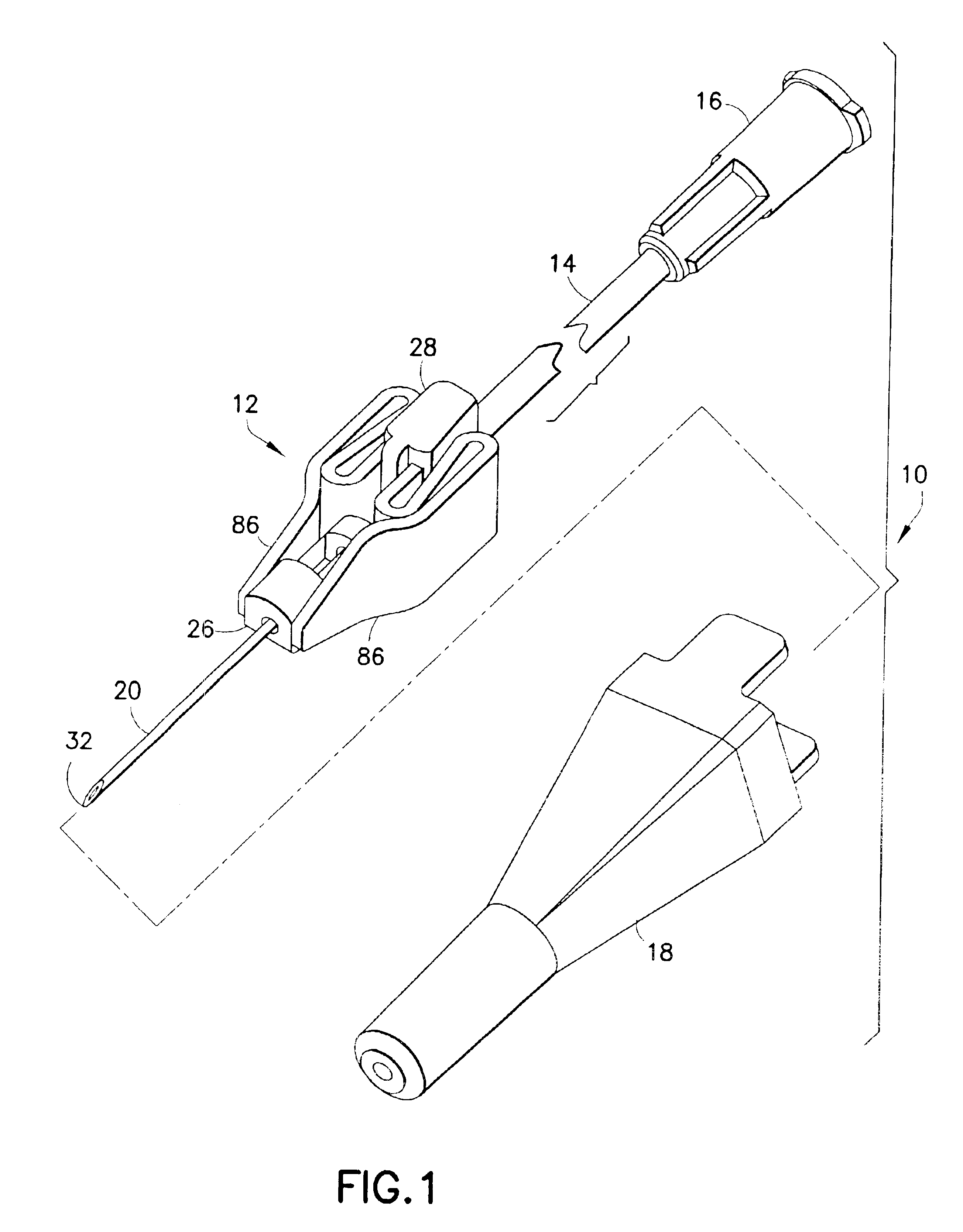
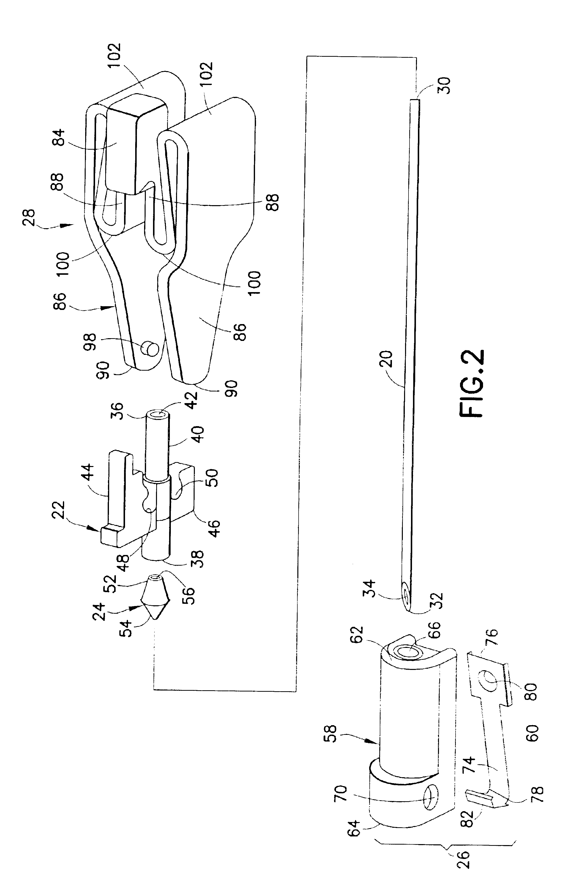
The passive shield assembly further includes a pair of resiliently deflectable leaves. The leaves have proximal ends that are connected to opposite respective sides of the hub. The leaves further have distal ends connected to opposite sides of the tip guard. A portion of each leaf between the ends is resiliently collapsible onto itself and into close overlying relationship to the needle hub. Thus, the collapsed leaves can be gripped manually by the medical practitioner to manipulate the needle assembly prior to and during veinipuncture. However, a release of forces on the collapsed leaves enables the leaves to resiliently move toward an undeflected condition in which the leaves extend substantially linearly and parallel to one another on opposed sides of the needle cannula. This resilient unfolding of the leaves transports the tip guard distally along the needle cannula. The leaves have lengths sufficient to enable the tip guard to move into shielding engagement with the tip of the needle cannula, without moving distally beyond the needle cannula.
A medical practitioner employs the needle set of the subject invention by gripping the collapsed leaves of the shield assembly between a thumb and forefinger at a location proximally of the packaging cover. The packaging cover then is removed, and the tip of the needle cannula is inserted into a blood vessel of a patient. Upon completion of the insertion, the medical practitioner releases the grip on the collapsed leaves, and the leaves begin to unfold due to their inherent resiliency. The unfolding of the leaves causes the tip guard to move distally along the needle cannula. The distal movement of the tip guard will terminate when the tip guard contacts the skin of the patient. After completion of the medical procedure, the practitioner grabs the needle hub with a thumb and forefinger and pulls the needle cannula from the patient. This relative proximal movement of the needle cannula permits the leaves to unfold further, thereby moving the tip guard into surrounding relationship to the tip of the needle cannula. The clip or other such structure within the tip guard prevents a re-exposure of the used needle cannula.

Problems solved by technology

Accidental sticks with a needle are painful and can lead to infection.
Additionally, an accidental stick with a used needle can transmit disease.
This reshielding procedure can lead to the accidental needle stick that the medical practitioner is trying to avoid.
As a result, it often is difficult to access and release the latch.
Furthermore, there is a significant potential for unreliable performance of the very small coil spring that had been stored in a compressed state for a long time.
However, the exposed used needle cannula creates a substantial risk prior to completion of the shielding.
Furthermore, there are many occasions where the needle of a blood collection set or an IV infusion set is pulled out, intentionally or unintentionally, by a patient.
In still other instances, the medical practitioner will inadvertently drop the used needle cannula immediately after withdrawal from the patient or during a shielding attempt.
This attempt to retrieve the falling needle cannula creates a significant possibility for an accidental needle stick.

Method used


Image

  • Passive safety device for needle of IV infusion or blood collection set
  • Passive safety device for needle of IV infusion or blood collection set
  • Passive safety device for needle of IV infusion or blood collection set

Examples


third embodiment

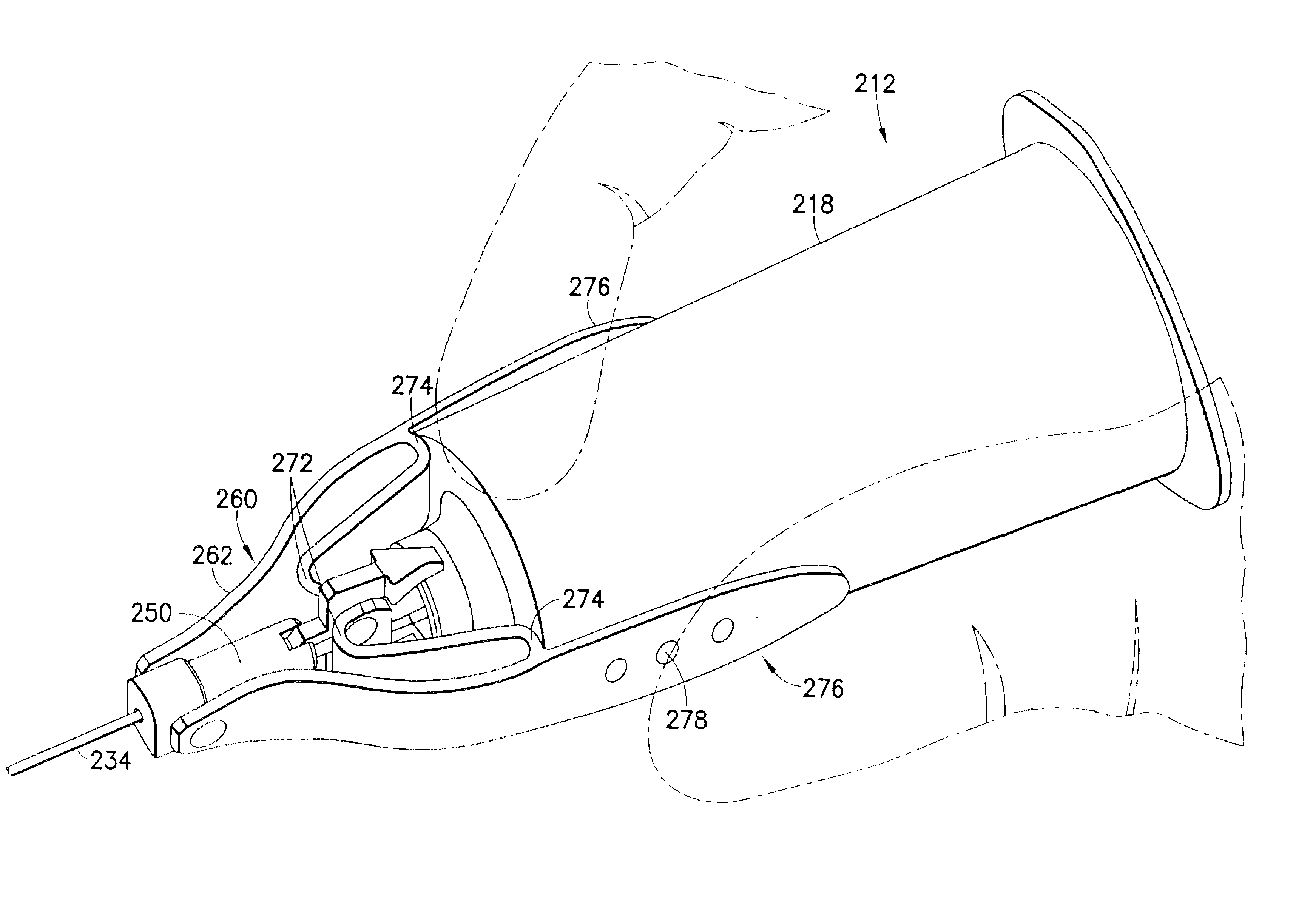
FIGS. 9-17 show a blood collection needle assembly 210 according to the invention and adapted for use with a tube holder. Holder 212 includes a proximal end 214, a distal end 216 and a tubular sidewall 218 extending between the ends. Proximal end 214 is widely open, as shown in FIGS. 12 and 17, and is configured for slidably receiving an evacuated tube, such as the VACUTAINER® brand of evacuated tubes sold by Becton Dickinson and Company. Distal end 216 of holder 212 includes an end wall 220 that extends in from tubular sidewall 218. End wall 220 includes a mounting collar 222 with a mounting aperture 224 for receiving needle assembly 210, as described below. Mounting aperture 220 is provided with structure for releasably engaging needle assembly 210. As illustrated herein, mounting aperture 224 of mounting collar 220 is configured for a threaded connection. However, other embodiments may have other mounting structures, such as grooves, ribs or a bayonet connection. Still other arra...

first embodiment

Needle assembly 210 further includes an IV packaging cover 280 that is similar to packaging cover 18 described with respect to the In particular, IV packaging cover 280 performs a dual function of preventing an inadvertent stick with pointed distal end 238 of needle cannula 234 prior to use of needle assembly 210. Additionally, IV packaging cover 280 holds leaves 262 in their collapsed condition for maintaining tip guard assembly 250 in its proximal position. IV packaging cover 280 differs slightly from packaging cover 18 in that open proximal end 282 of IV packaging cover 280 is formed with opposed cut-outs 284 for accommodating folded leaves 262. Needle assembly 210 further may include a non-patient packaging cover (not shown) frictionally mounted over proximal portions of needle hub 226 and protectively covering non-patient end 342 of needle cannula 234 prior to use.

Needle assembly 210 is used with tube holder 212 substantially as shown in FIGS. 9-17. In particular, the non-pati...


PUM


Abstract

A passively shieldable needle assembly set is provided for use with a tube holder. The assembly includes a needle cannula, a hub mounted to the needle cannula and a tip guard slidably movable along the needle cannula. The tip guard can be slid into a distal position where the tip of the needle cannula is safely shielded. A collapsible guard drive is mounted to the hub and includes a pair of collapsible leaves extending from the hub to the tip guard. The leaves have a length that enable the tip guard to move into shielding engagement around the tip of the needle cannula, while preventing complete removal of the tip guard from the needle cannula. The leaves are resiliently deformable and can be collapsed onto themselves and onto the hub. The leaves can be retained in their collapsed condition by a packaging cover and subsequently by the grip of a medical practitioner. A mere release of the grip on the collapsed leaves enables the leaves to resiliently return toward an undeflected condition and propels the tip guard distally into shielding engagement around the tip of the needle cannula.

Description

BACKGROUND OF THE INVENTION1. Field of the InventionThe subject invention relates to a passively activated safety shield for a needle, such as the needle for an IV infusion set, a blood collection set or a fluid collection tube holder.2. Description of the Related ArtA prior art blood collection set or IV infusion set includes a needle cannula having a proximal end, a pointed distal end and a lumen extending between the ends. The proximal end of the needle cannula is securely mounted in a plastic hub with a central passage that communicates with the lumen through the needle cannula. Thin flexible thermoplastic tubing is connected to the hub and communicates with the lumen of the needle cannula. The end of the tubing remote from the needle cannula may include a fixture for connecting the needle cannula to a blood collection tube or some other receptacle. The specific construction of the fixture will depend upon the characteristics of the receptacle to which the fixture will be connec...

Claims


Application Information

Patent Timeline
Patent Type & Authority Patents(United States)
IPC IPC(8): A61B5/15A61M5/32A61M25/06A61M5/158A61M25/00
CPCA61B5/1405A61B5/1438A61B5/1444A61M5/3275A61M25/0625A61M5/3213A61M2005/325A61M5/326A61B5/15003A61B5/150259A61B5/150389A61B5/150496A61B5/150572A61B5/150732A61B5/150587A61B5/150519A61B5/150648A61B5/15074A61B5/154
Inventor SAULENAS, WILLIAM G.NIERMANN, VOLKERWILKINSON, BRADLEY M.
Owner BECTON DICKINSON & CO
Learn More