
Cable terminal

a cable terminal and terminal technology, applied in the direction of cable junctions, coupling device connections, contact members penetrating/cutting insulation/cable strands, etc., can solve the problems of insufficient alignment of the cores to the contact elements, inability to ensure the alignment of the channel middle, and inability to ensure the alignmen

Inactive Publication Date: 2005-02-15
PHOENIX CONTACT GMBH & CO KG
View PDF28 Cites 18 Cited by
  • Summary
  • Abstract
  • Description
  • Claims
  • Application Information

AI Technical Summary

Benefits of technology

Thus, one primary object of this present invention is to make available a cable terminal for end-face connection of the conductors of a multicore cable in which alignment of the individual cores to the contact elements of the plug part is accomplished as precisely as possible. In addition, within certain limits, different cables with different core cross sections may be connected with the same cable terminal.
The embodiment of the core holding and guiding part in accordance with the present invention enables connection of different cables with different core cross sections. By the arrangement of the core guidance channels in the first section of the core holding and guiding part which consists of soft material, especially of a soft plastic such as a thermoplastic elastomer, the cross section of the core guidance channels can be reduced to the smaller cross section of the cores by radial pressure on this first section. In doing so, as a result of the elastic properties of the first section, sufficient clamping of the individual cores into the core guidance channels can be achieved so that the cores are prevented from slipping back when the contact elements penetrate into the cores. Moreover, the radial pressure on the first section provides the contact force necessary for making electrical contact between the individual strands of a conductor and the contact element which has been pushed into the conductor from the end face. Thus, the force acting radially on the core insulation additionally supports the restoration force of the core insulation. Because the alignment of the cores or the conductors to the contact elements is accomplished by a positioning aid formed in the second section of the core holding and guiding part, exact alignment of the conductors to the contact elements is not influenced by the core guidance channels being pressed together. Because the second section consists of a hard plastic such as a hard thermoplastic or a ceramic material or other hard insulating material, the positioning aid is much less sensitive to aging and settling phenomena.
According to one especially preferred embodiment of the invention, the first section is made in one piece from thermoplastic elastomer and the second section is made in one piece from thermoplastic. Here, the core holding and guiding part can be produced in a two-component injection molding process so that the two sections are connected to one another materially. The advantage of this core holding and guiding part which is made as a composite injected part is that in this way, it is easily ensured that the first section and the second section cannot slide or turn relative to one another.
The arrangement and alignment of the contact elements centered to the holes of the positioning aid can advantageously be accomplished especially easily by the holes of the first tapering area which adjoins the core guidance channels having a second area of constant diameter and a third, widening area. The positioning aid is then used not only to align the cores, but at the same time, also to align the contact elements so that exact alignment of the cores to the contact elements is accomplished by the hole overall and thus, all three areas having a coincident center line.
According to one advantageous embodiment of the cable terminal in accordance with the present invention, the cable receiver has a sleeve with an outside thread and the plug part has a union nut with an inside thread which corresponds to the outside thread of the sleeve. Thus, to assemble the cable terminal in the invention, the cable receiver and the plug part can be easily screwed together, the core holding and guiding part being located between the cable receiver and the plug part.
The radial force on the core holding and guiding part can be easily produced by the plug part's having a sleeve part which is located within the union nut, the sleeve part in the installed state surrounding the core holding and guiding part and the inside diameter of the sleeve part being at least partially smaller than the outside diameter of the core holding and guiding part. A radial force can thus, be applied to the first section of the core holding and guiding part by the arrangement of this sleeve part in the plug part in which the core guidance channels are squeezed together and the cores which have been inserted into the core guidance channels are secured. Especially advantageous clamping of the cores in the core guidance channels in the vicinity of the positioning aid is achieved by the inside diameter of the sleeve part widening in the direction to the core holding and guiding part. In other words, the sleeve part has the smallest diameter on the side facing away from the cable receiver.

Problems solved by technology

If a cable which is used has cores with smaller diameters than the core guidance channels, the alignment of the cores to the contact elements is inadequate.
But here, the disadvantage is that by squeezing together the rubber elastic material of the core holding and guiding part, not only is the channel cross section changed, but also the alignment of the channel middle to the contact elements are changed.
Thus, insertion of cores with different diameters into the core guidance channels of the core holding and guiding part is indeed possible, but the accuracy of alignment of the inserted cores to the contact elements likewise, depends on the core cross sections used so that exact alignment cannot always be ensured.
In addition, the alignment of the cores is adversely affected by aging and settling phenomena of the rubber elastic core holding and guiding part.

Method used


Image

  • Cable terminal
  • Cable terminal
  • Cable terminal

Examples


Embodiment Construction

Initially, reference is made to the definitions provided previously. In addition, as also noted above, the term “cable terminal” as used herein refer to both terminals which connect a cable to an electrical device as well as to joining devices that connect two cables together.

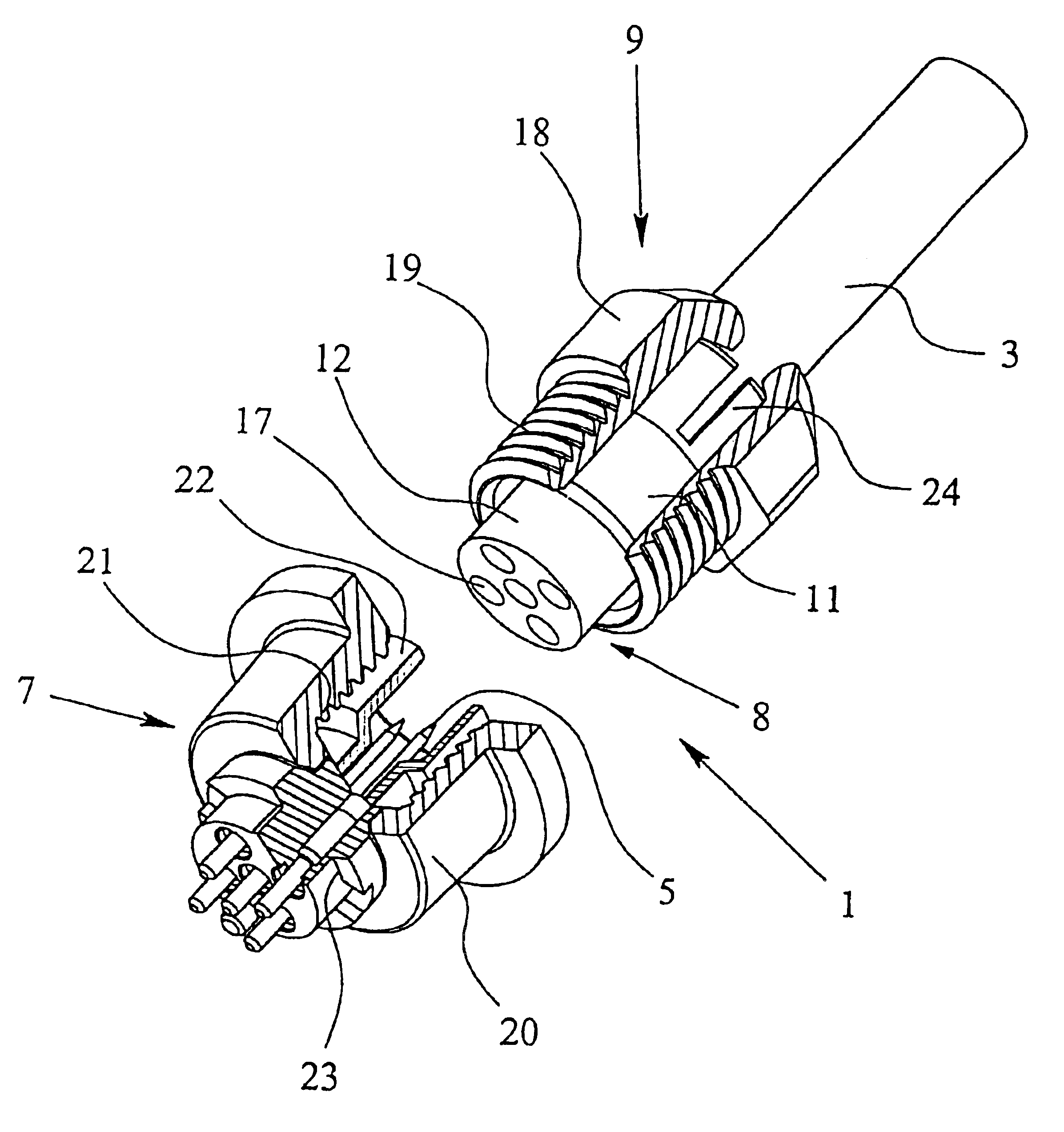
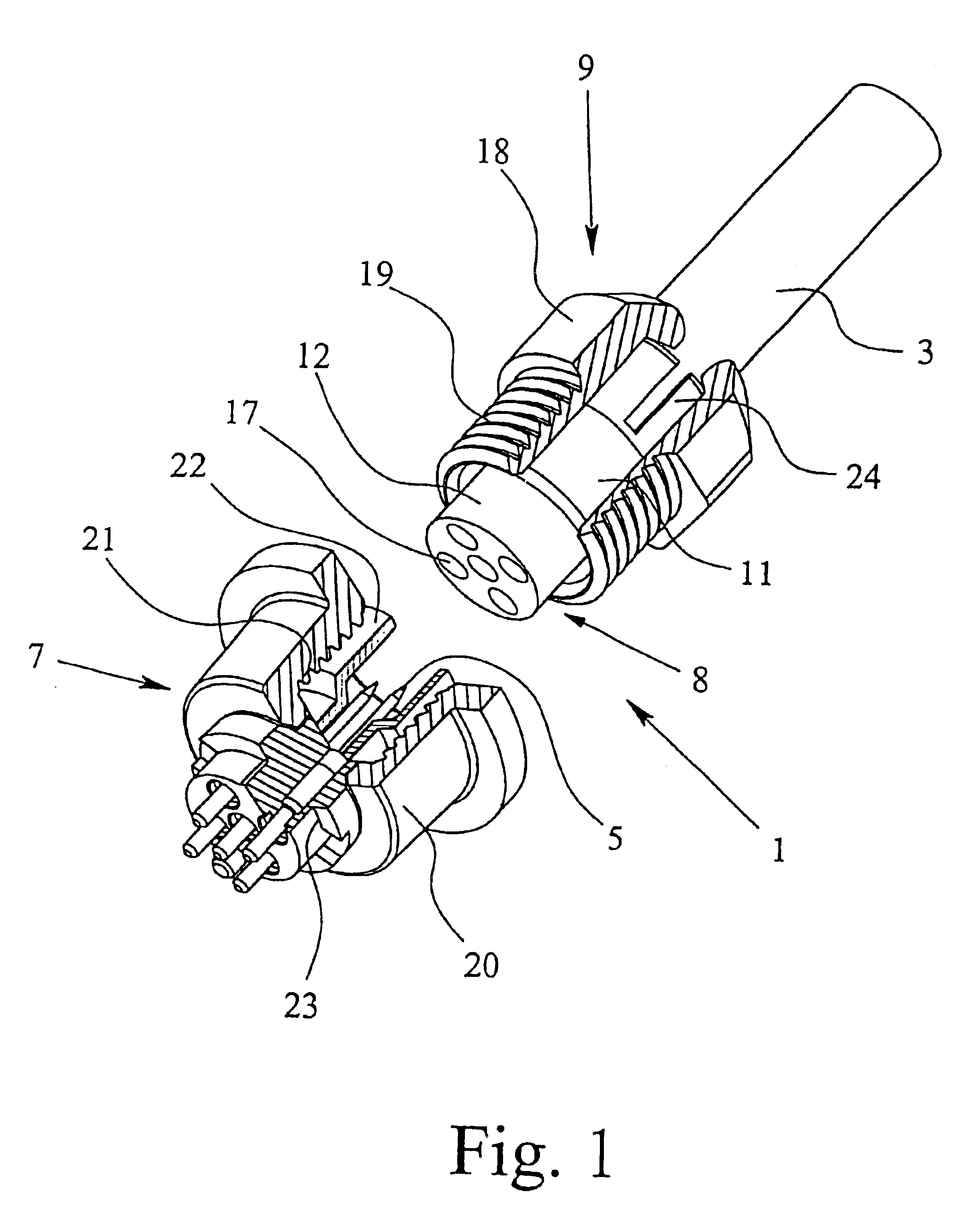
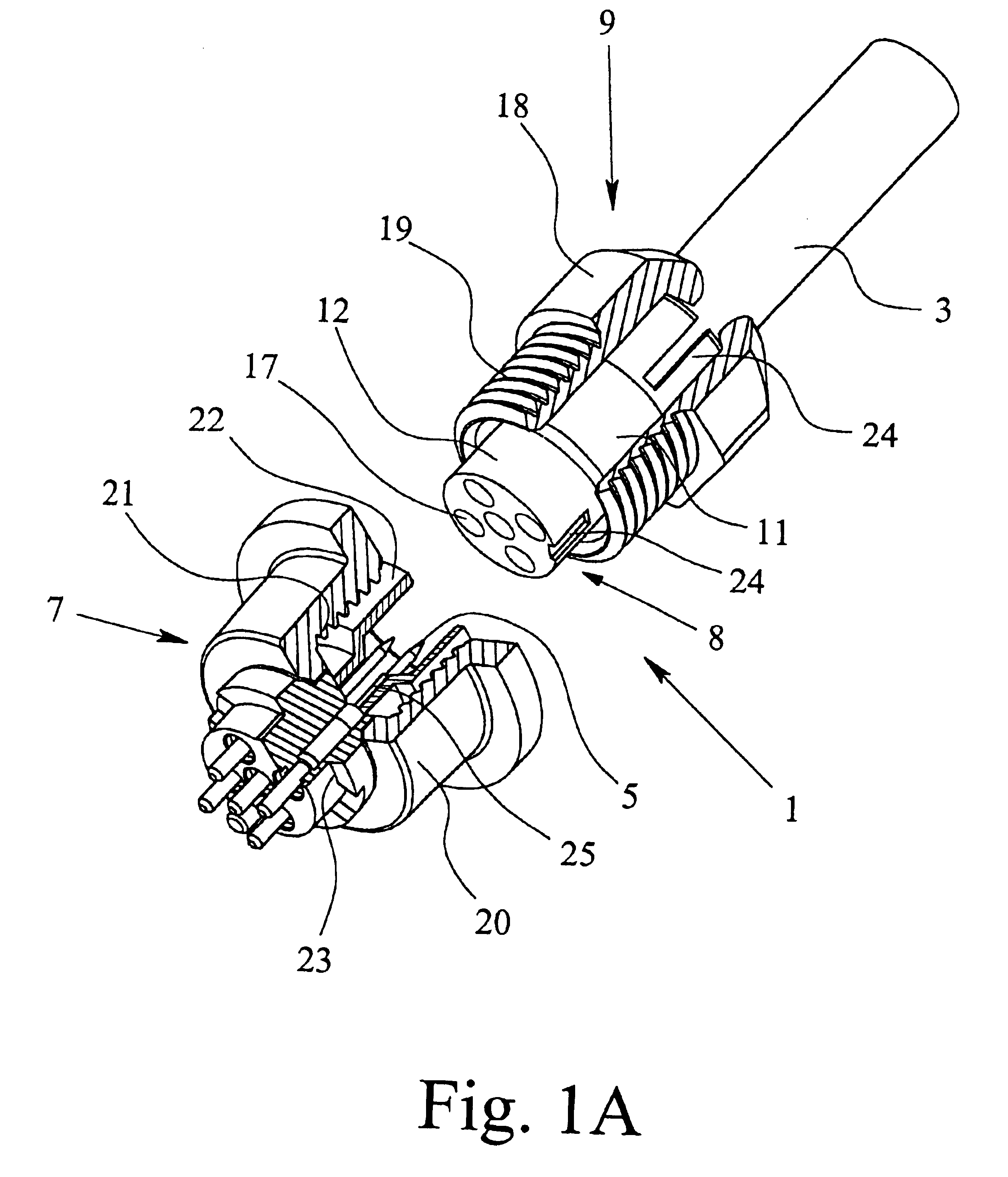
FIGS. 1 and 2 show one embodiment of a cable terminal 1 in accordance with the present invention for end-face connection of the conductors of a multicore cable 3 which are more clearly shown in FIGS. 3 and 4, the multicore cable having a total of five cores 4. The cable terminal 1 enables connection of unstripped conductors 2 shown in FIGS. 3 and 4 by the contact elements 5 penetrating into the conductor 2 from the end face of the conductor 2 roughly in the direction of the lengthwise axis of the conductor 2 in the manner shown in FIG. 4. In doing so, generally stranded conductors 2 are used so that the contact element 5 penetrates between the individual strands of the conductor 2. As a result of the restoratio...


PUM


Abstract

Cable terminal for end-face connection of the conductors of a preferably multicore cable. The cable terminal includes a plug part provided with contact elements, a core holding and guiding part, and a cable receiver. The core holding and guiding part includes core guidance channels, and the plug part and the and the cable receiver can be connected to one another. In the assembled state, the core holding and guiding part is located between the plug part and the cable receiver. Alignment of the individual cores to the contact elements of the plug part is accomplished by the core holding and guiding part which includes a first section of soft material, and a second section of hard material. In the first section, core guidance channels is provided while in the second section, a positioning aid is formed for exact alignment of the conductors to the contact elements.

Description

BACKGROUND OF THE INVENTION1. Field of the InventionThe present invention relates to cable terminals for end-face connection of the conductors of a multicore cable, the cable terminal having a plug part and a cable receiver that can be connected to one another, especially screwed to one another. In particular, the present invention relates to such cable terminals where the plug part is provided with contact elements and a core holding and guiding part with guidance channels where in the assembled state, the core holding and guiding part is located between the plug part and the cable receiver.2. Description of Related ArtInitially, it will be explained below the meaning of the terms used herein below both with respect to the prior art and the present invention as well.a) The term “cable” means an electrical line which has at least one core, but generally several cores. If there are several cores, it is a multicore cable. For cables with only one core, it is a single-core cable.b) The...

Claims


Application Information

Patent Timeline
IPC IPC(8): H01R13/58H01R13/59
CPCH01R13/59
Inventor JACKE, JOACHIM
Owner PHOENIX CONTACT GMBH & CO KG
Learn More