Droplet target delivery method for high pulse-rate laser-plasma extreme ultraviolet light source

a laser-plasma, high-pulse technology, applied in the field of laser-plasma, extreme ultraviolet light source, can solve the problems of adversely affecting successive droplets in the stream, damage or destruction of successive droplets, damage to sensitive optical components,

Inactive Publication Date: 2005-02-15
UNIV OF CENT FLORIDA RES FOUND INC +1
View PDF5 Cites 61 Cited by
  • Summary
  • Abstract
  • Description
  • Claims
  • Application Information

AI Technical Summary

Benefits of technology

In accordance with the teachings of the present invention, a laser-plasma, EUV radiation source is disclosed that controls the target droplet delivery rate so that designated target droplets are not affected by the ionization of preceding droplets. In one embodiment, the source nozzle has an orifice of a predetermined size that allows the droplets of the desired size to be emitted at a rate set by the target material's natural Rayleigh instability break-up frequency, as generated by a piezoelectric transducer. The rate of the droplet generation is determined by these factors in connection with the pulse frequency of the excitation laser so that buffer droplets are delivered between the target droplets. The buffer droplets act to absorb radiation generated from the ionized target droplet so that the next target droplet is not affected.

Problems solved by technology

The size of the orifice is set so that as the droplets freeze and are reduced in size, they are of a size at the ionization region where ionization by a high intensity laser pulse will generate significant EUV radiation, without allowing pieces of frozen xenon to escape ionization, and possibly damage sensitive optical components.
Due to this proximity, a target droplet currently being ionized adversely affects successive droplets in the stream.
Thus, the successive droplets are damaged or destroyed prior to being ionized by the laser beam.
However, this would result in plasma formation very close to the nozzle orifice, providing an excessive heat load and causing plasma-induced erosion of the nozzle orifice.
However, operating the transducer at a frequency other than the Rayleigh break-up frequency adversely affects the ability to create a consistent stream of droplets.
Drop on demand generators are difficult to control to provide droplets of the right size at the right time because of the surface tension properties of liquid xenon.
However, this leads to droplets of too large a size for the laser ionization process, possibly causing component damage resulting from unionized frozen xenon.

Method used


Image

  • Droplet target delivery method for high pulse-rate laser-plasma extreme ultraviolet light source
  • Droplet target delivery method for high pulse-rate laser-plasma extreme ultraviolet light source

Examples


Embodiment Construction

The following discussion of the embodiments of the invention directed to a nozzle for an EUV radiation source is merely exemplary in nature, and is in no way intended to limit the invention or its applications or uses.

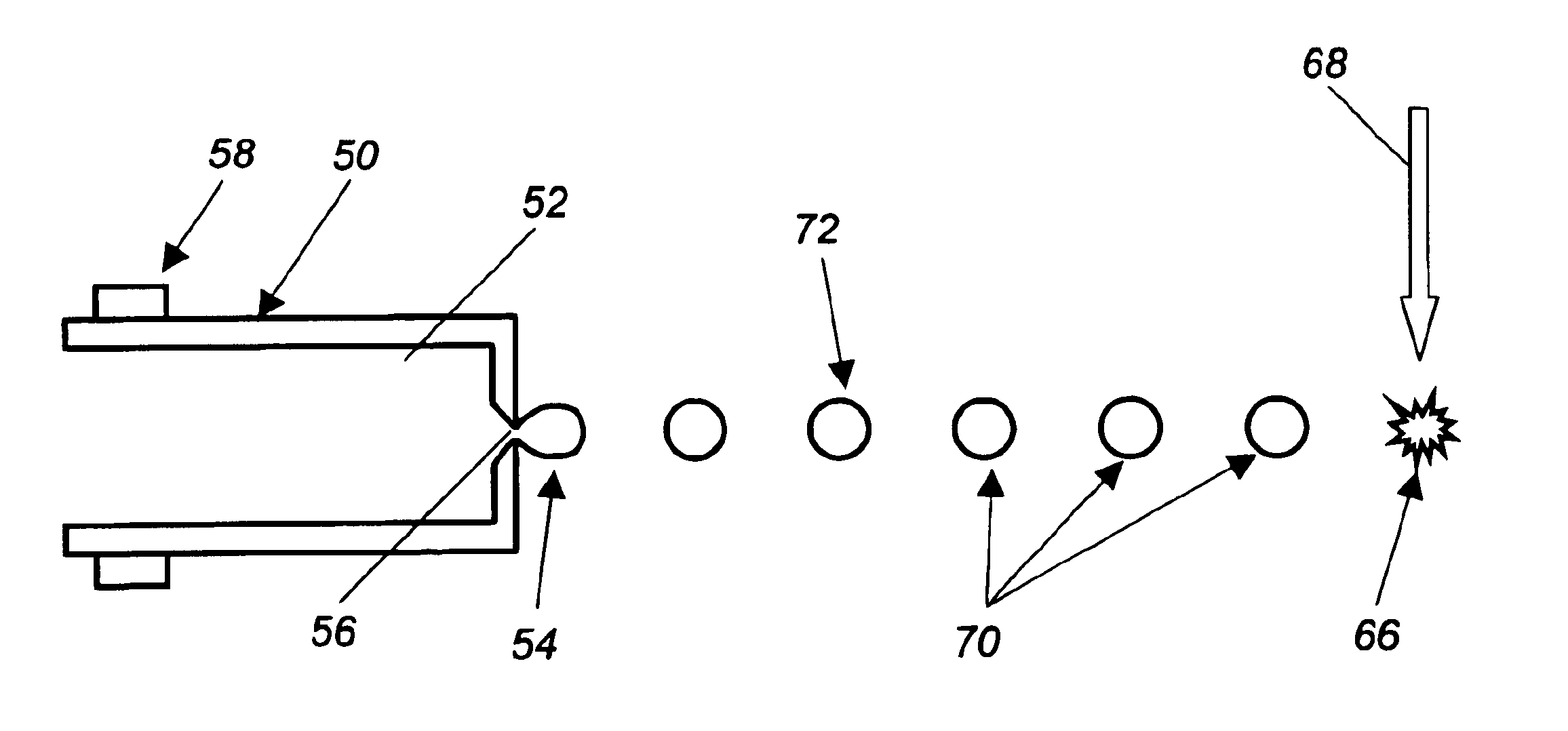
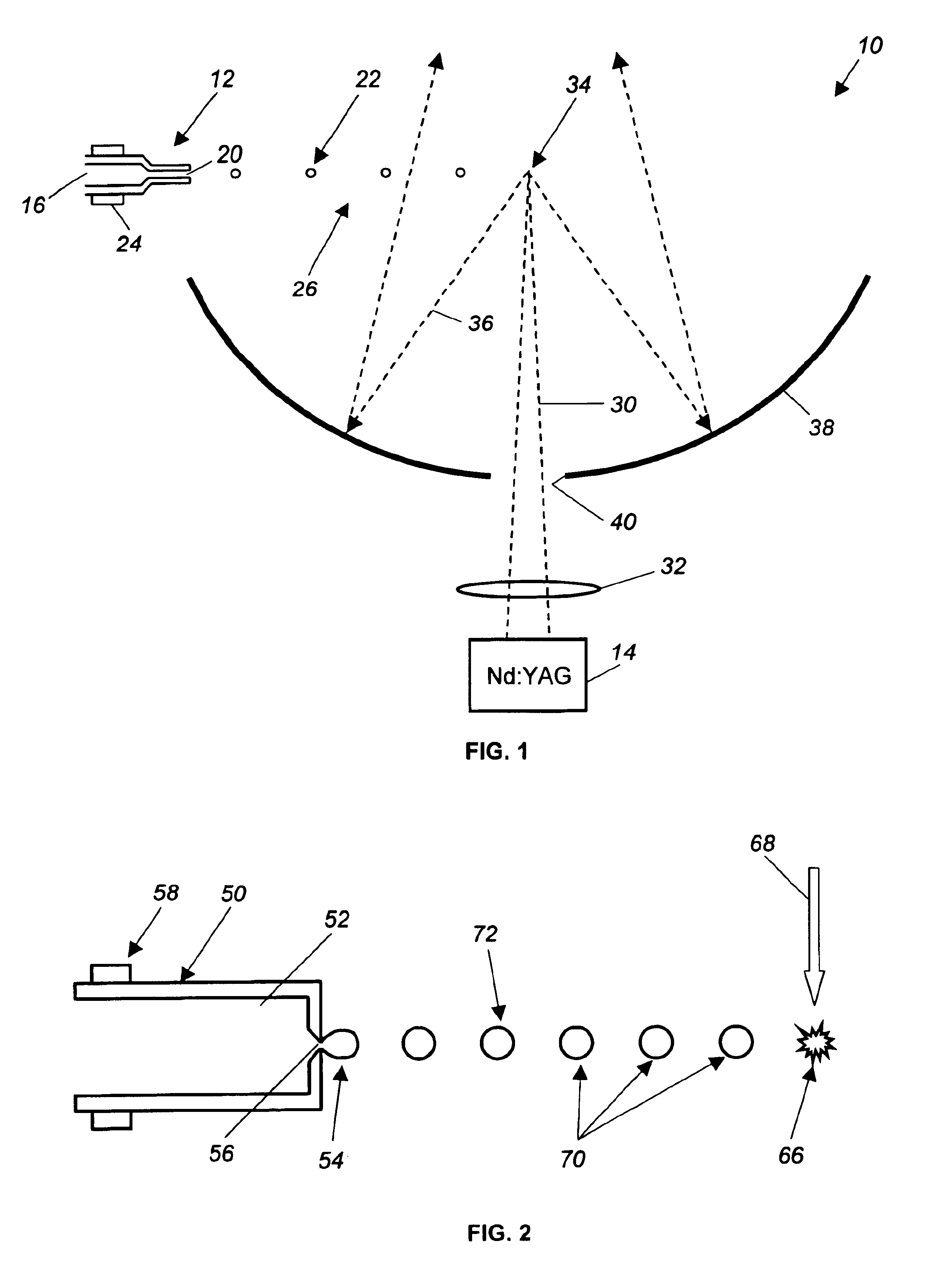
FIG. 1 is a plan view of an EUV radiation source 10 including a nozzle 12 and a laser beam source 14. A liquid 16, such as xenon, flows through the nozzle 12 from a suitable source (not shown). The liquid 16 is forced under pressure through an exit orifice 20 of the nozzle 12 where it is formed into a stream 26 of liquid droplets 22 directed to a target location 34. A piezoelectric transducer 24 positioned on the nozzle 12 perturbs the flow of liquid 16 to generate the droplets 22.

A laser beam 30 from the source 14 is focused by focusing optics 32 onto the droplet 22 at the target location 34, where the source 14 is pulsed relative to the rate of the droplets 22 as they reach the target location 34. The energy in the laser beam 30 ionizes the droplet 22 and generates a...


PUM


Abstract

A laser-plasma, EUV radiation source (10) that controls the target droplet delivery rate so that successive target droplets (66, 72) are not affected by the ionization of a preceding target droplet. A source nozzle (50) of the source (10) has an orifice (56) of a predetermined size that allows the droplets (54) to be emitted at a rate set by the target materials natural Rayleigh instability break-up frequency as generated by a piezoelectric transducer (58). The rate of the droplet generation is determined by these factors in connection with the pulse frequency of the excitation laser (14) so that buffer droplets (70) are delivered between the target droplets (66, 72). The buffer droplets (70) act to absorb radiation generated from the ionized target droplet (66) so that the next target droplet (72) is not affected.

Description

BACKGROUND OF THE INVENTION1. Field of the InventionThis invention relates generally to a laser-plasma, extreme ultraviolet light source and, more particularly, to a laser-plasma, extreme ultraviolet light source that provides synchronized laser pulses and a target droplet delivery rate so that buffer droplets are provided between consecutive target droplets.2. Discussion of the Related ArtMicroelectronic integrated circuits are typically patterned on a substrate by a photolithography process, well known to those skilled in the art, where the circuit elements are defined by a light beam propagating through or reflected from a mask. As the state of the art of the photolithography process and integrated circuit architecture becomes more developed, the circuit elements become smaller and more closely spaced together. As the circuit elements become smaller, it is necessary to employ photolithography light sources that generate light beams having shorter wavelengths and higher frequencie...

Claims


Application Information

Patent Timeline
Patent Type & Authority Patents(United States)
IPC IPC(8): H05G2/00G21K5/00G21K5/02G21K5/08H01L21/027H05G1/00H05H1/24
CPCH05G2/008H05G2/003
Inventor SHIELDS, HENRY
Owner UNIV OF CENT FLORIDA RES FOUND INC
Why Eureka
Try Eureka