
VCO with automatic calibration

a voltage control and automatic calibration technology, applied in the direction of pulse automatic control, oscillation generator, modulation, etc., can solve the problems of phase noise, degraded performance, and special challenges in pll design

Inactive Publication Date: 2005-02-15
QUINTIC MICROELECTRONICS WUXI
View PDF6 Cites 37 Cited by
  • Summary
  • Abstract
  • Description
  • Claims
  • Application Information

AI Technical Summary

Benefits of technology

In another embodiment included in the present invention, apparatus is provided for generating a latch signal that samples the output of a window comparator. The apparatus comprises a differentiating circuit coupled to the control signal of the phase-locked loop that produces a derivative signal, an absolute function circuit that operates on the derivative signal and produces a settling error signal, and a comparator that toggles every time the settling error drops below a prescribed threshold and thus provides the latch signal.
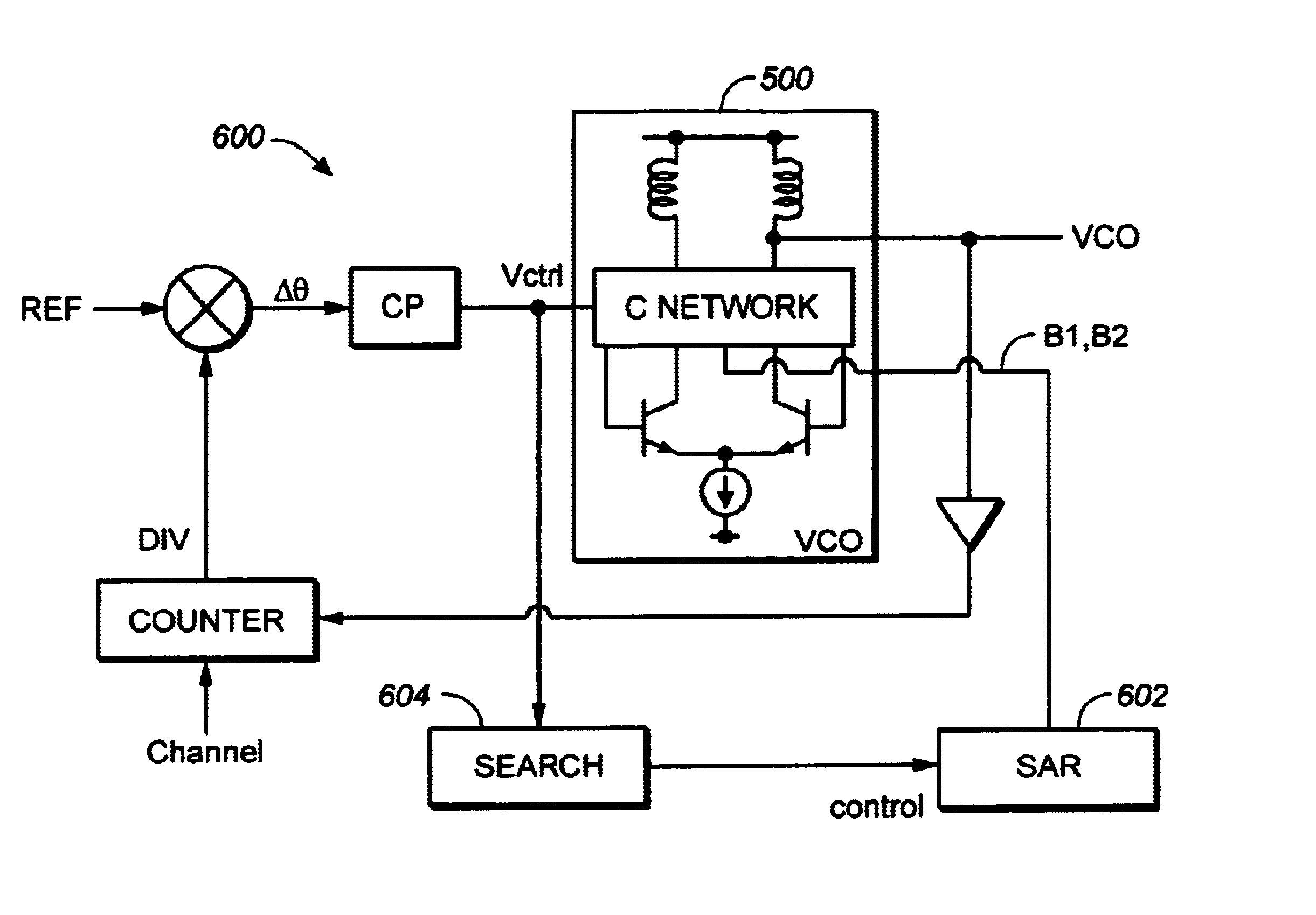
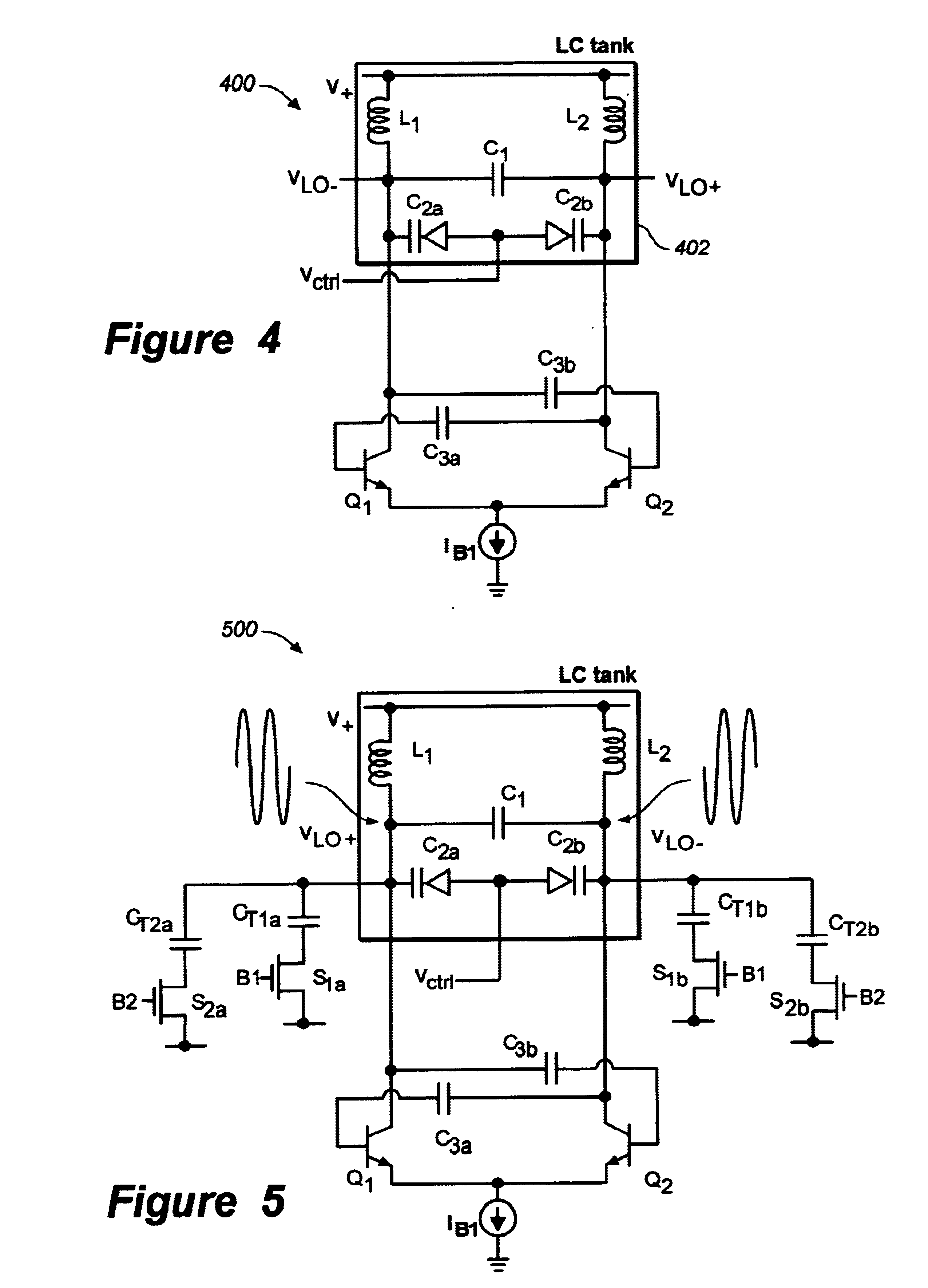
In another embodiment, a communication device is provided that comprises a PLL and associated VCO, wherein the VCO comprises an LC resonant tank circuit and the communication device further comprises apparatus for automatic calibration of the VCO. The apparatus comprises a plurality of coarse-tuning capacitors, and a plurality of switches operable to selectively connect the plurality of coarse-tuning capacitors to the LC resonant tank circuit based on a VCO control voltage.

Problems solved by technology

However, using a conventional VCO to cover such a wide frequency band or multiple bands produces degraded performance and phase noise.
This makes the PLL design especially challenging.

Method used


Image

  • VCO with automatic calibration
  • VCO with automatic calibration
  • VCO with automatic calibration

Examples


Embodiment Construction

In one or more embodiments, a PLL system that includes automatic calibration and coarse tuning of a voltage-controlled oscillator is provided.

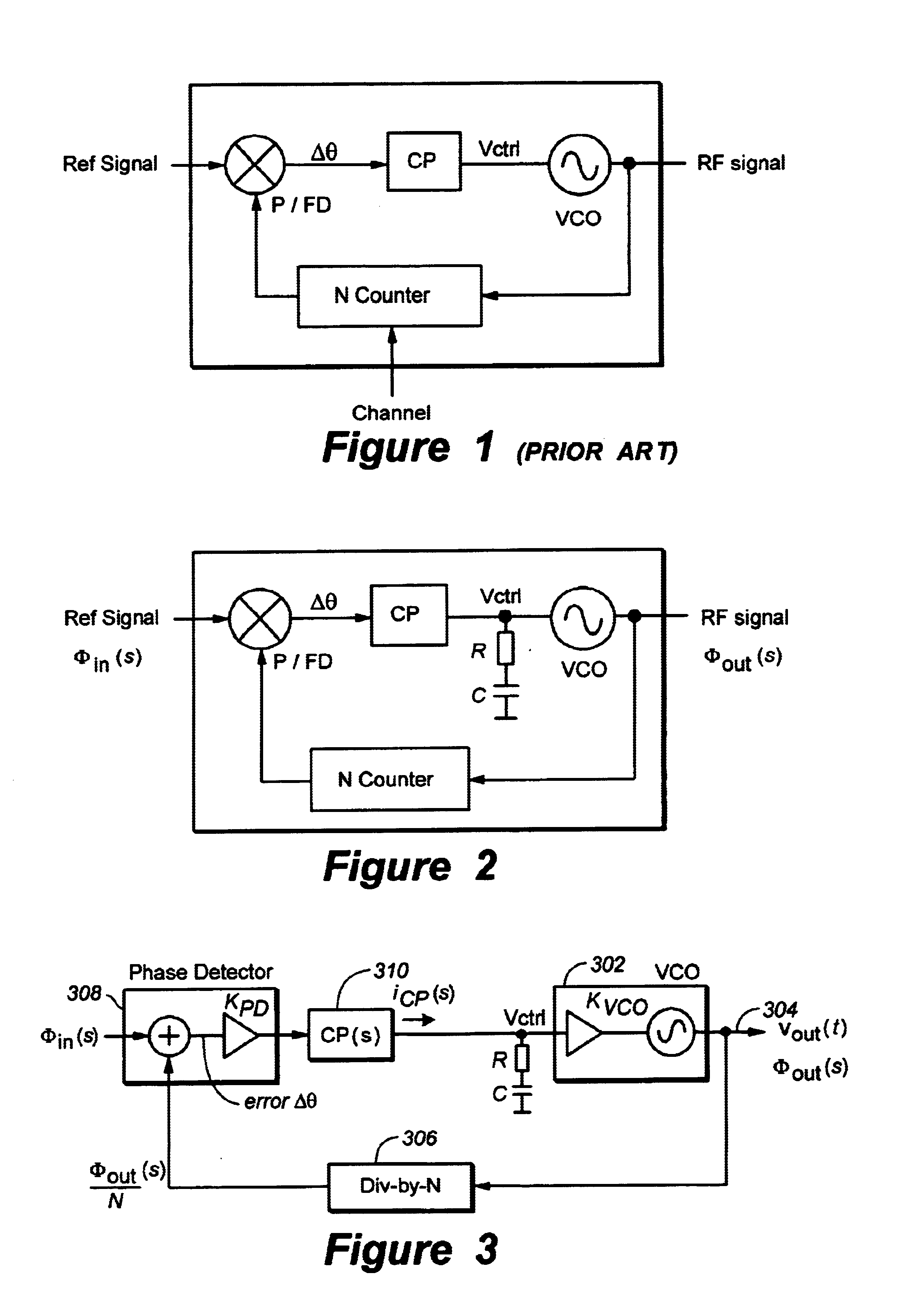
FIG. 2 shows a PLL feedback system used to synthesize a radio frequency (RF) carrier signal. The system comprises a voltage-controlled oscillator (VCO), N counter, phase / frequency detector (P / FD), charge pump (CP), and integration filter. The integration filter comprises resistor (R) and capacitor (C).

FIG. 3 shows a mathematical model of the PLL system of FIG. 2. The VCO 302 produces an output signal 304 at a frequency set by control voltage νcrtl, which can be expressed as;

νout(t)=Ac cos(ωfreet+Kvco∫νctrl(t)dt)

where ωfree is the free-running frequency of the oscillator and Kvco is its gain function. The gain function Kvco describes the relationship between the excess phase of the carrier Φout(s) and the control voltage νctrl, i.e.; Φout⁡(s)νctrl⁡(s)=Kvcos

The N counter 306 simply divides the output phase Φout(s) by N. When the PLL is locked, ...


PUM


Abstract

Voltage-controlled oscillator with apparatus for automatic calibration. The voltage-controlled oscillator includes switches connecting associated coarse-tuning capacitors to an LC resonant tank of the oscillator. The voltage-controlled oscillator also comprises a calibration loop used to appropriately set the switches associated with the coarse tuning apparatus based on a oscillator control signal.

Description

FIELDThe present invention relates generally to voltage-controlled oscillators, and more particularly, to automatic calibration of voltage-controlled oscillators with coarse tuning elements to operate over a wide frequency band or multiple frequency bands.BACKGROUNDVoltage-controlled oscillators (VCO) are critical components in phase-locked loop (PLL) circuits used to synthesize radio frequencies in communication transceivers. A typical PLL circuit is shown in FIG. 1. The PLL implements a feedback system and consists of a VCO, N counter, phase / frequency detector (P / FD) and charge pump (CP). The feedback drives the phase difference (□θ) between the reference signal (Ref) and the output of the N counter towards zero by creating a control voltage νcrtl that adjusts the VCO to the proper frequency and phase offset. When locked, the PLL generates an output signal (RF signal) with a frequency fVCO equal to;fVCO=NfREF where N is the value of the N-counter and fREF is the frequency of the r...

Claims


Application Information

Patent Timeline
Patent Type & Authority Patents(United States)
IPC IPC(8): H03B5/08H03B5/12H03B1/00H03L7/099H03L7/10H03L7/18
CPCH03L7/099H03L7/10H03L7/18H03B5/1265H03B5/1231H03B5/1215H03B5/1243H03B2201/0208Y10S331/02
Inventor GROE, JOHNAUSTIN, JOSEPH
Owner QUINTIC MICROELECTRONICS WUXI
Learn More