Feed network and method for an offset stacked patch antenna array

a patch antenna array and feed network technology, applied in the field of patch antennas, can solve the problems of low-profile dish antennas that may only decrease the overall height by two to four inches, not optimally directed, and inadequate gain at typical satellite elevation

Inactive Publication Date: 2005-02-15
KVH IND INC
View PDF25 Cites 17 Cited by
  • Summary
  • Abstract
  • Description
  • Claims
  • Application Information

AI Technical Summary

Benefits of technology

A feed network for an array of antenna elements disposed in a plurality of columns may comprise a plurality of feed points, for each of a plurality of antenna elements in the array, a first connection point on the element and a second connection point on the element, for each of two or more of the feed points, one or more feed lines connecting the feed point to connection points of a plurality of antenna elements, wherein the locations of the first and second connection points on a specified element are disposed such that the feed lines connected thereto preferentially collect rad

Problems solved by technology

However, low profile dish antennas may only decrease overall height by two to four inches.
Planar antennas suffer in that maximum gain may be orthogonal to the plane of the antenna, thus not optimally directed at a satellite, which may be 60° from that direction.
However, gain may vary as the cosine of the

Method used


Image

  • Feed network and method for an offset stacked patch antenna array
  • Feed network and method for an offset stacked patch antenna array
  • Feed network and method for an offset stacked patch antenna array

Examples


Embodiment Construction

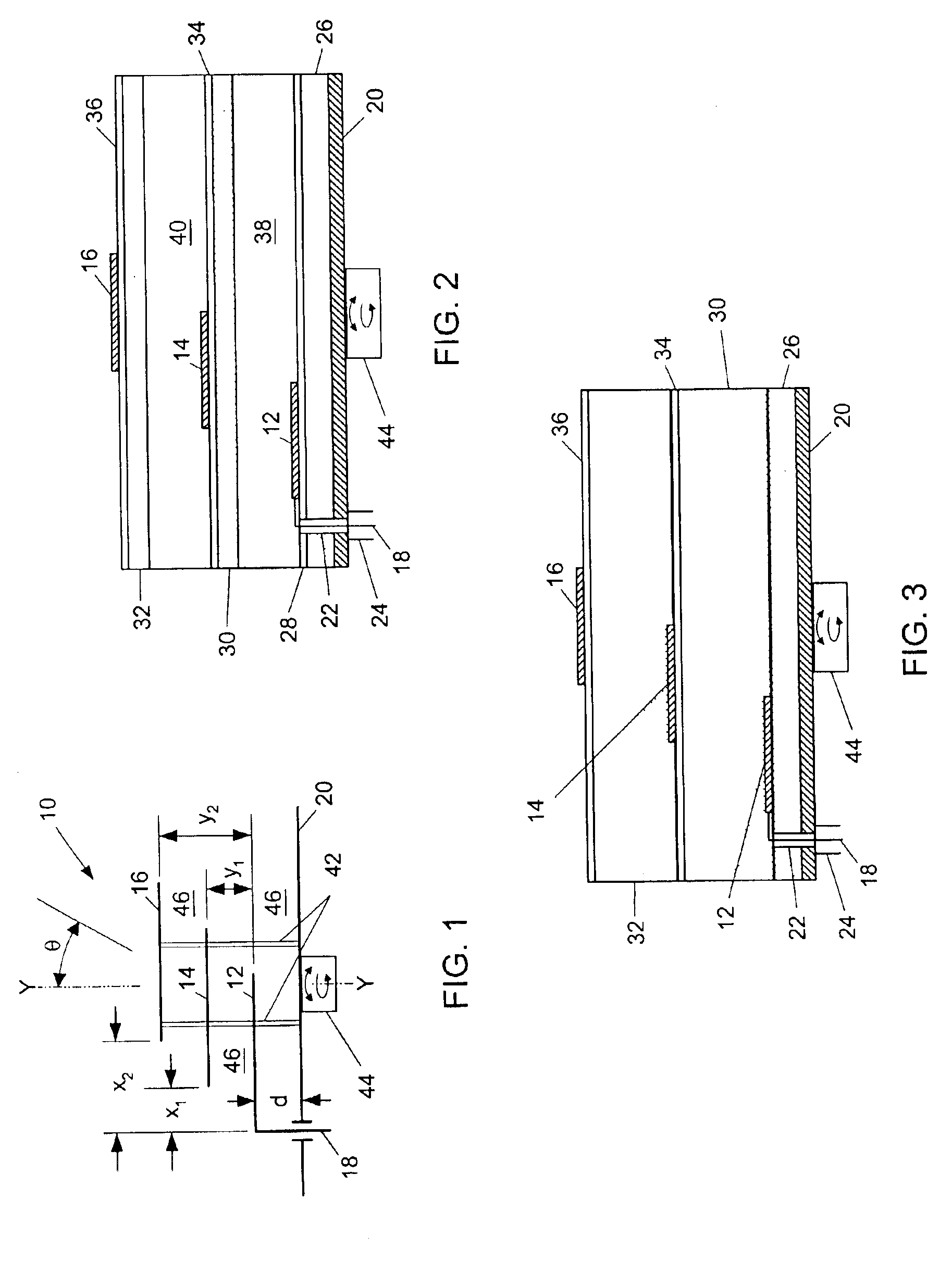
Referring now to FIG. 1, there is illustrated a schematic view of a stacked patch antenna 10. In the illustrative embodiment of FIG. 1, antenna 10 may include three antenna elements 12, 14 and 16. However, it can be understood that the number of elements may not be limited to three and that two or more elements may be used. The antenna elements may be fabricated of metal, metal alloy, or other conducting materials as are known in the art. In one embodiment, the elements 12, 14 and 16 are preferably microstrip antenna elements. Microstrip antenna elements are known in the art and are planar metallic elements that are formed on a continuous dielectric substrate using conventional integrated circuit manufacturing techniques, e.g., photolithography. Other forms and fabrications of antenna elements known to those of ordinary skill in the art also may be employed.

It will be appreciated that elements 12, 14 and 16 are shown in a side view in FIG. 1, with the planar surfaces of elements 12,...


PUM


Abstract

A feed network for, and method of feeding, an array of antenna elements has multiple feed points. Two feed lines extend from the feed points, one having a longer length that the other to provide a phase difference in the two feed lines. The feed lines split into main feed lines, which in turn split into secondary feed lines that connect to the antenna elements. The connections to the elements fed from one of the feed lines are rotated with respect to the connections to the elements fed from the other to provide another phase difference between the elements. The antenna elements may be fed from the longer of the feed lines from one of the feed points and the shorter of the feed lines from an adjacent feed point, with the connections from the feed points providing for right hand and left hand circular polarized elements, respectively.

Description

FIELDThis application relates to the field of patch antennas, and more particularly to feed networks for stacked patch antennas using offset multiple elements to control the direction of maximum antenna sensitivity.BACKGROUNDMany satellite mobile communication applications require that the direction of maximum sensitivity or gain of a receiving antenna be adjusted; i.e., that the receiving antenna be directed towards the satellite and track the satellite while the vehicle is moving and turning.Typically, in the continental United States television satellites may be between 30° and 60° above the horizon. In mobile satellite television applications, operating in a 12 GHz range, standard dish antennas may be mounted on the vehicle and mechanically rotated to the appropriate azimuth and tilted to the appropriate elevation to track the satellite.While such systems may provide adequate signal acquisition and tracking, the antenna, tracking mechanism and protective dome cover may present a...

Claims


Application Information

Patent Timeline
IPC IPC(8): H01Q9/04H01Q21/00H01Q21/06
CPCH01Q9/0414H01Q21/065H01Q21/0075
Inventor MCCARRICK, CHARLES D.
Owner KVH IND INC
Why Eureka
Try Eureka