Digital camera having a printing function in which a movable camera part is moved from an in-use position to an out-of-use position during printing

a digital camera and printing function technology, applied in the direction of printers, cameras, instruments, etc., can solve the problems of not considering the behavior of the camera, not considering the practicability of the product level, and not considering the behavior of the member

Inactive Publication Date: 2005-02-15
MINOLTA CO LTD
View PDF9 Cites 38 Cited by
  • Summary
  • Abstract
  • Description
  • Claims
  • Application Information

AI Technical Summary

Problems solved by technology

In the foregoing digital camera combined with the printer, however practical usability on the product level has not been considered.
Specifically, consideration has not been given to the behavior of the camera during a printing operation which may take a longer period of time than a shooting operation in the camera.
In particular, consideration has not been given to the behavior of a member for performing a protruding operation or the like with respect to the main body of the camera during the printing operation.
If attention is focused on the operation of a lens barrier and a lens barrel, fore example, the lens barrel protruding from the open barrier during the printing operation will cause the whole camera to lose balance.
In addition, the camera may tip over as a result of vibration during the printing operation.
In that case, the lens may break or become damaged.
There is also the possibility that the apparatus may sway from being off balance during printing, which may adversely affect the result of printing.
A pop-up flash would similarly cause the whole camera to lose balance if the pop-up flash is in a popped-up state, i.e., in use.

Method used


Image

  • Digital camera having a printing function in which a movable camera part is moved from an in-use position to an out-of-use position during printing
  • Digital camera having a printing function in which a movable camera part is moved from an in-use position to an out-of-use position during printing
  • Digital camera having a printing function in which a movable camera part is moved from an in-use position to an out-of-use position during printing

Examples


Embodiment Construction

Preferred Embodiments of the Invention

Hereinafter, embodiments of the present invention will be described with reference to the drawings.

Referring now to the drawings, a digital camera having a printing function according to an embodiment of the present invention will be described.

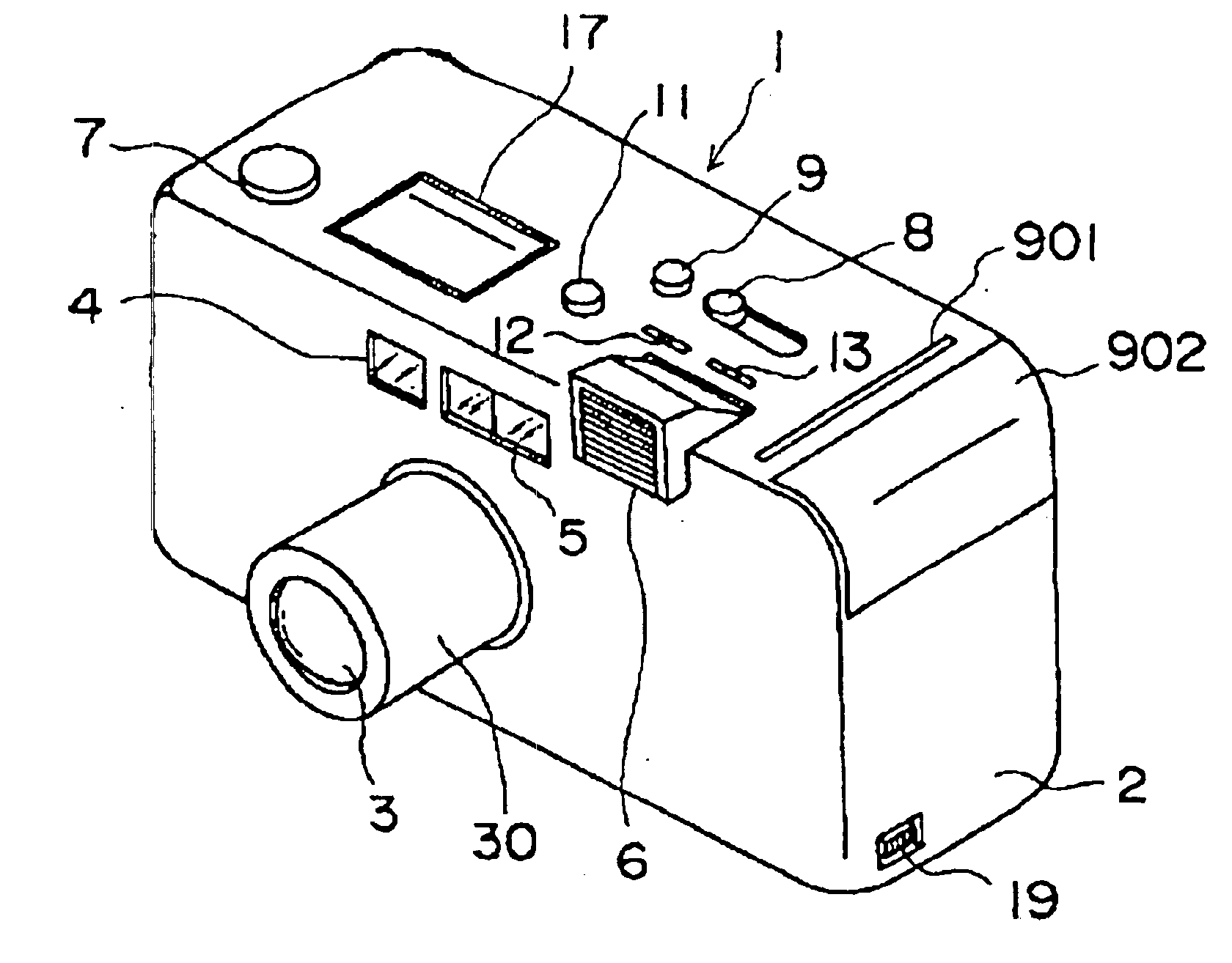
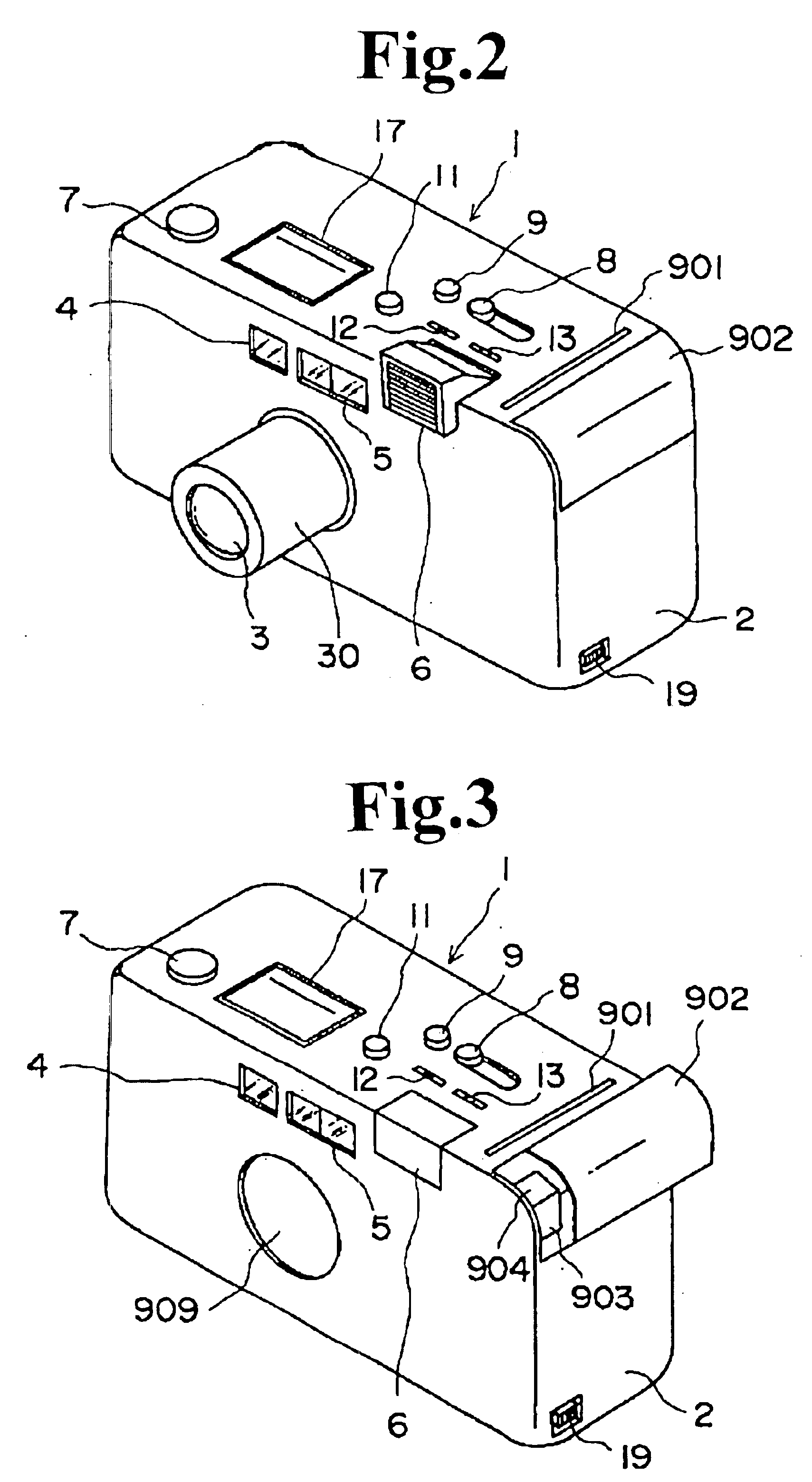
FIGS. 2 to 5 are overall perspective views of the digital cameral in accordance with the present invention.

In the drawings, 1 denotes a camera main body and 2 denotes a printer unit portion internally provided with components required to perform a printing operation, as will be described later.

The front face of the camera main body 1 is provided with: a shooting lens finder window 4; an AF unit 5 for automatic focus detection (hereinafter referred to as AF); and a flash 6 which pops up from the main body. A lens barrel 30 for holding the shooting lens 3 has been so constructed as to be extendable from and retractable into the camera main body 1. When the lens barrel 30 has collapsed, a lens barrier 909 is ...


PUM


Abstract

There is provided a digital camera having a printing function, the camera having a moving member for moving from an out-of-use position to an in-use position to perform a shooting operation, a selector for selecting a printing operation to be performed, and a controller for bringing the moving member into the out-of-use position in response to the selection of the printing operation by the selector.

Description

This application is based on the application No. 11-178295 filed in Japan, the content of which is hereby incorporated by reference.BACKGROUND OF THE INVENTION1. Technical Field of the InventionThe present invention relates to a digital camera having a printing function.2. Description of the Related ArtA digital camera having a printing function is well known. For example, a digital camera combined with a printer is disclosed in Japanese Unexamined Patent Publication No. HEI 3-29471.In the foregoing digital camera combined with the printer, however practical usability on the product level has not been considered. Specifically, consideration has not been given to the behavior of the camera during a printing operation which may take a longer period of time than a shooting operation in the camera. In particular, consideration has not been given to the behavior of a member for performing a protruding operation or the like with respect to the main body of the camera during the printing o...

Claims


Application Information

Patent Timeline
Patent Type & Authority Patents(United States)
IPC IPC(8): H04N5/225H04N5/232G03B11/04H04N5/765G03B17/02G03B17/04G03B17/48G03B17/50G03B29/00H04N1/21H04N5/781H04N5/907
CPCH04N1/2112H04N1/2154H04N5/2252H04N5/23241H04N5/23248H04N1/00925H04N5/23287G03B17/04G03B17/48G03B29/00H04N5/23258H04N2101/00H04N23/50H04N23/51H04N23/60H04N23/68H04N23/6812H04N23/687
Inventor YAMAMOTO, KOJIMURAKAMI, TOHRUISHII, TORUFUKUDA, AKIRATANAKA, YOSHIHARUMINATO, SHOICHI
Owner MINOLTA CO LTD
Why Eureka
Try Eureka