Visual device

a technology of visual devices and electrodes, applied in the field of visual devices, can solve the problems of too expensive devices to accurately calculate information, difficult for this device to count the number of cells, and difficult to accurately calculate edge information in terms of cell contour, etc., and achieve the effect of easy correction of parameters and easy correction of parameters

Inactive Publication Date: 2005-02-15
ECCHANDES
View PDF7 Cites 53 Cited by
  • Summary
  • Abstract
  • Description
  • Claims
  • Application Information

AI Technical Summary

Benefits of technology

On the other hand, in a case of appending the means for vibrating the digital image to the visual device described in claim 2, the present invention is described as follows: The means for separating the all-object areas from the background by using the all-object formed edge-information image can classify the pixels within the background and the pixels within the all-object areas, which are distinguished by the edge information of all of the objects, into some different groups. In the means for detecting the position and the size of the all-object areas, then, one pixel represents gravity center of the all-object areas and the number of the pixels within the all-object areas. Each of the means can be carried out in parallel. In the means for generating the all-object rough edge-information image, the means for generating the all-object formed edge-information image, the means for separating the all-object areas from the background and the means for detecting the position and the size of the all-object areas, respectively, each pixel of their images can also be derived in parallel. Moreover, all these means are realized by local processing. The visual device, therefore, can count the all-object area number fast, without depending on form and size of all of the objects. The visual device can use for many applications because the all-object areas separated by the edge information from the background are seldom influenced by lighting and so on, as compared to the case of detecting the all-object areas by classification of color information, and the edge information, moreover, is generated by using refraction and reflection, without coloring all of the objects even though they are transparent. Therefore, many problems on counting all of the objects are solved very well.
The invention described in claim 12 is a visual device comprising array operation units arranged in the shape of a lattice in a data processing device that realizes means for separating object areas by using a formed edge-information image, wherein each of the array operation units comprises: means for arranging the array operation units in the shape of a lattice; means for connecting a nonlinear oscillator in the array operation unit with nonlinear oscillators in its neighbors in terms of link values; means for initializing the array operation unit; means for finishing processing if there is not the formed edge-information image to input any more; means for inputing a band-pixel value in the formed edge-information image; means for computing an external noise; means for computing a neighbor input summation of the nonlinear oscillator; means for computing parameters in the nonlinear oscillator; means for computing an output of the nonlinear oscillator; means for computing a contour parameter; means for computing a border parameter; and means for outputing a band-pixel value in an object-area image including the object areas separated by the nonlinear oscillator. In short, this is the enforcement form of an algorithm for realizing a function generating the object-area image, which is offered by the array operation units by using digital technology. After the array operation units were arranged in the shape of a lattic, followed by connecting the neighbor array operation units each to each, and by initializing each parameter in the array operation units, the present invention inputs the formed edge-information images every pixel if necessary, and carries out a sequence of processes from computing the external noise to outputing each band-pixel value in the object-area image, one by one. The present invention repeats a sequence of these processes until the formed edge-information image comes not to be imputed. Since the present invention can use a general processor, the parameter can be corrected easily. Note that the array operation units does not always have to carry out waiting for receiving each of the parameters and some neighbor pixels in each type of the images exactly, which are sent from the neighbor array operation units. Because the array operation units waiting for receiving can use their parameters and band-pixel values instead of the parameters and the band-pixel values in each type of the images, which can not be received from the neighbor array operation units. Although each of the parameters and a pixel in each type of the images generated by the array operation units may have a little noise in this case, each means in the present invention absorbes almost all of the noise. Border processing and time-out processing are realized simultaneously and easily by the means for superseding by their own parameters and band-pixel values.

Problems solved by technology

In any cases that some troubles happen in dying chromosome purple and chromosome can not be dyed purple, however, it is difficult for this device to count the number of the cells, because the cells are transparent in general and color information is no good for making the whole cell a lump.
Even though the device can catch a core and some Mitochondrias of an expanding cell image, this way can not always be used, and many devices calcurate edge information in terms of contour of the cells appeared by refraction and reflection of light.
Although the edge information should theoretically make the whole cell a lump, the devices complement the edge information by the form and size of the cell since the edge information is often incomplete in fact.
In addition, since the devices must calcurate optical flow and so on, in order to select moving cells from all cells, the devices are too expensive to calcurate information exactly.
Otherwise, the cheap devices lose much time.
However, even though the devices find peculiar color information of objects from an image in order to count the number of these objects, it is very difficult for the devices to count the number, because the color information depends on brightness of solor light and lighting, and performance of a camera.
Another reason is the difficulty of classifying objects as targets or others when the objects are similar color in taking a image.
If a visual device regards variance of color information as movement of a object, lighting and camera performance seldom comes to be a problem, but it becomes more difficult for the device to reproduce form of the object exactly.
Moreover, painting out a domain surrounded for edge information makes a problem that the device must decide an object area.
In a case, however, that the visual device counts humans and animals walking in a room and along outdoors, it can be used for only limited targets if the camera is fixed, because the camera can not catch the whole room and the whole outdoor area, and an image of the humans and the animals becomes big or small, corresponding to distance from the camera.
Moreover, heavy computational complexity is desired for the visual device to recognize the objects since it must distinguish the humans and the animals from interior objects of the room.

Method used


Image

  • Visual device
  • Visual device
  • Visual device

Examples


Embodiment Construction

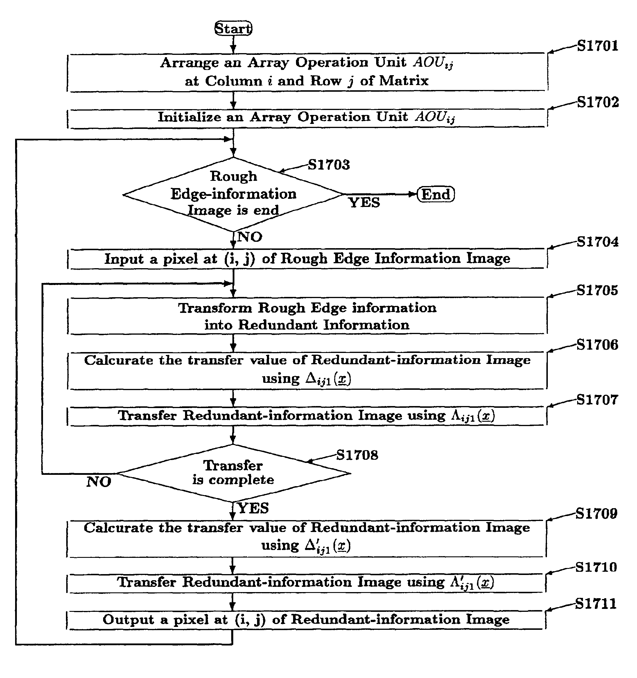
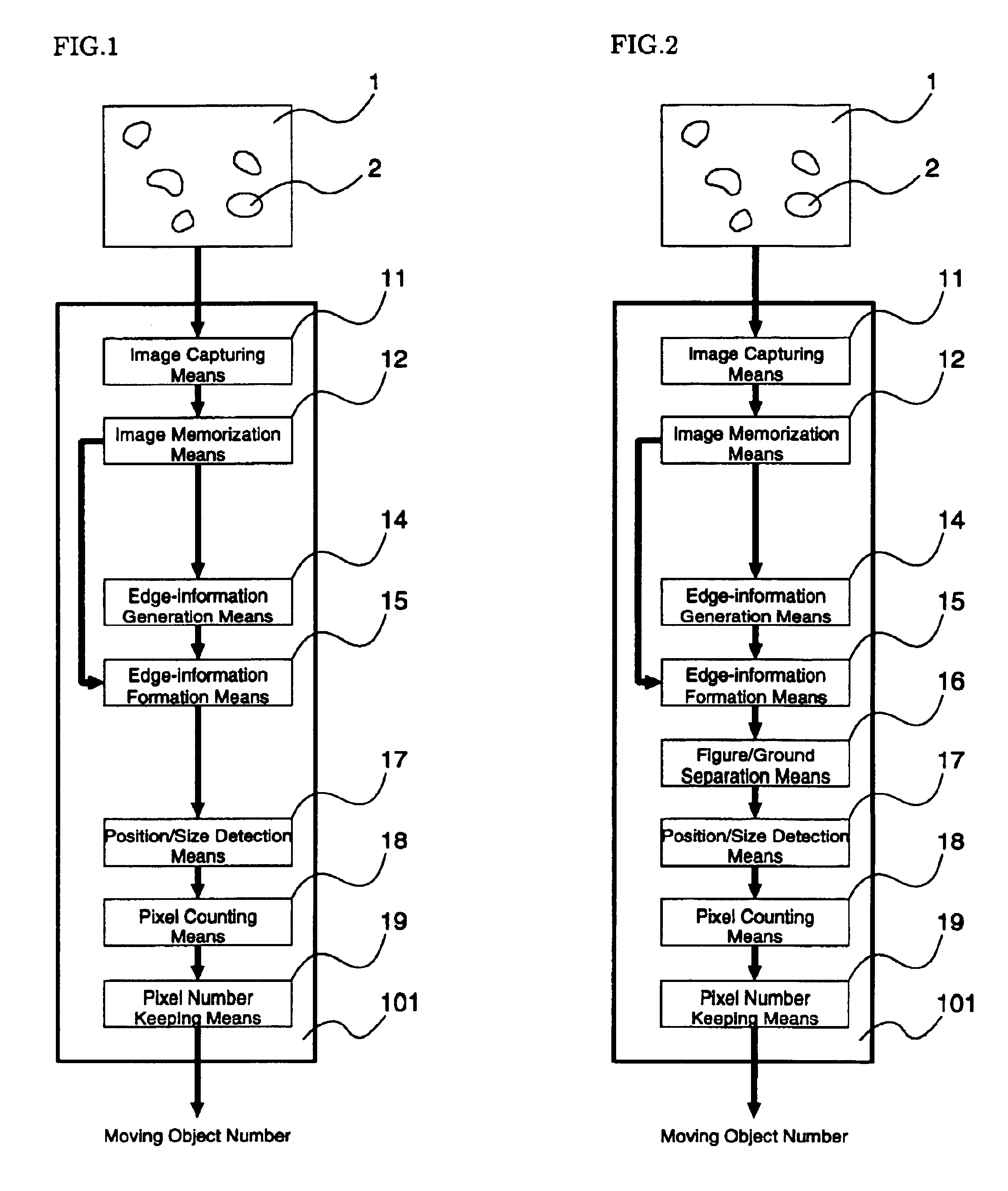
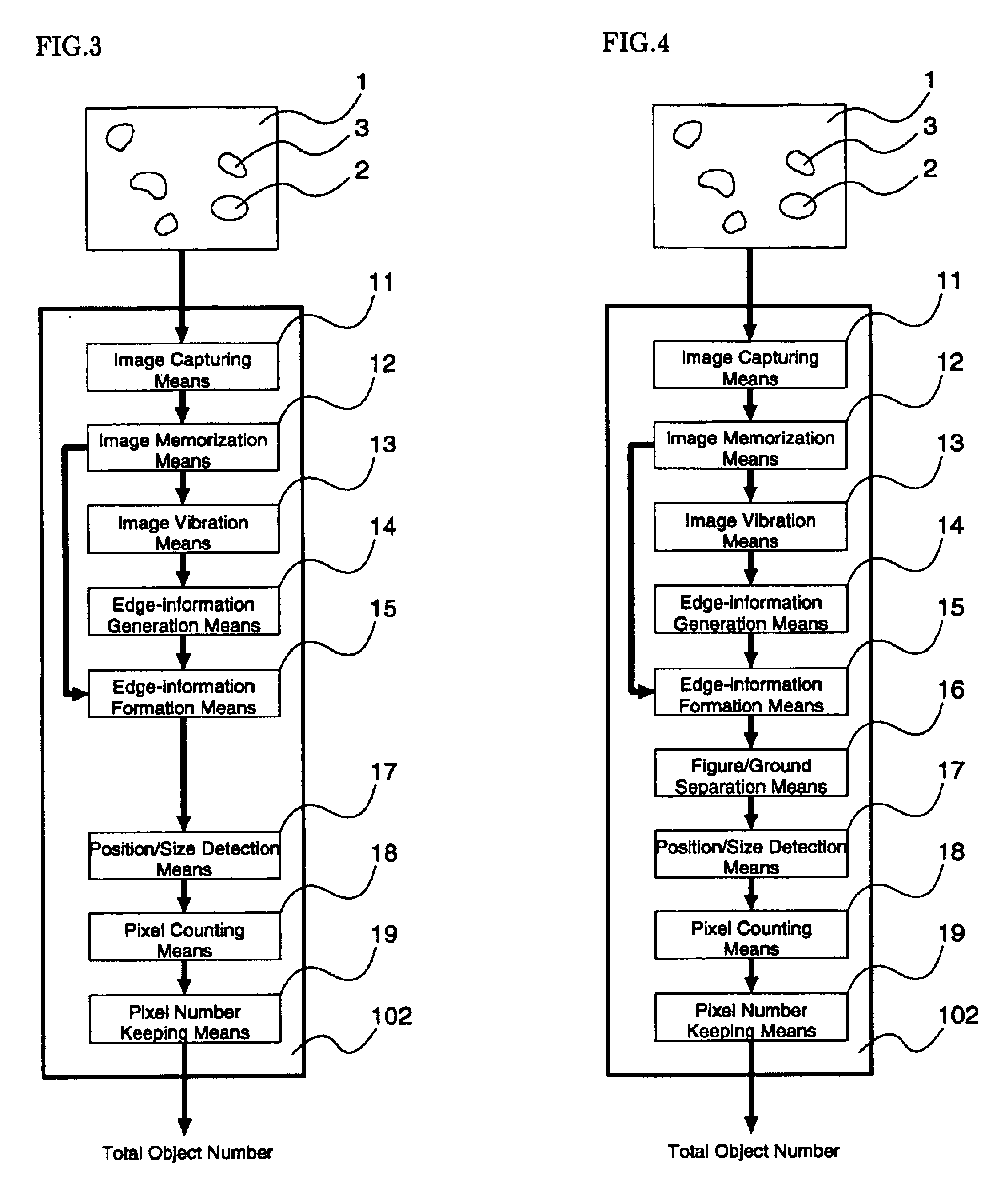
It is described below about these enforcement forms of twelve visual devices shown in FIG. 1 to FIG. 12. These enforcement forms are realized by using an image capturing means 11 (refer to FIG. 1), which translates frame image 1 receiving from a video camera to the suitable format and size of digital image 111, an image memorization means 12 (refer to FIG. 1), which memorizes a digital image 111 for a certain period, an image vibration means 13 (refer to FIG. 3), which vibrates the digital image 111 by digital circuits, an edge-information generation means 14 (refer to FIG. 1 and FIG. 3), which generates rough edge information 112 of moving objects 2 or still objects 3 from two digital images 111, an edge-information formation means 15 (refer to FIG. 1), which forms rough edge information 112 into exacter and clearer formed edge information 114, a figure / ground separation means 16 (refer to FIG. 2), which separates areas distinguished by formed edge information 114, a position / size ...


PUM


Abstract

A visual device searches for moving and still objects and counts the moving and still objects. The visual device includes a vibrator for vibrating a frame image by using an array calculating unit, an information unit for creating edge information on the moving and still objects from the frame image, a separator for separating the object region of the moving and still objects from the background of the frame image, a measuring unit for measuring the positions and sizes of the moving and still objects, a normalizer for normalizing the separation object regions segmented by the object regions, and a recognition unit for recognizing the normalized regions.

Description

FIELD OF THE INVENTIONThe present invention relates to a visual device counting some objects in an image and its assemble means, which can count the number of moving and still objects in the image consisting of such any bands of wave lengths as three primary colors, visible colors, infrared rays, ultra-violet rays, and so on.BACKGROUND OF THE INVENTIONMany digital devices using video cameras and digital cameras have been developed to count the number of objects in an image. These cameras, however, must take one image including the objects. An example is the device counting the number of cells in an image taken by a microscope. Since chromosome of the cells are dyed purple, the device can count the number of the cells, segmenting purple areas which are bigger than the regular size from the image and making them a lump. In any cases that some troubles happen in dying chromosome purple and chromosome can not be dyed purple, however, it is difficult for this device to count the number o...

Claims


Application Information

Patent Timeline
Patent Type & Authority Patents(United States)
IPC IPC(8): G06T5/00G06T7/20
CPCG06K9/0014G06T7/0012G06T7/0083G06T7/2033G06T2207/30024G06T2207/10016G06T2207/10056G06T7/12G06T7/246G06V20/695G06T7/20
Inventor AJIOKA, YOSHIAKI
Owner ECCHANDES
Why Eureka
Try Eureka