
Pig for detecting an obstruction in a pipeline

a technology for obstructions and pipelines, applied in the direction of measuring devices, electrical/magnetic diameter measurements, instruments, etc., can solve the problems of increasing the cost of replacement of damaged discs, high production costs, and undetected results

Inactive Publication Date: 2005-02-22
DONSA
View PDF10 Cites 19 Cited by
  • Summary
  • Abstract
  • Description
  • Claims
  • Application Information

AI Technical Summary

Benefits of technology

It is an object of the present invention to provide an obstacle monitoring or caliper pig which would be of a simple structure permitting relatively low manufacturing costs, monitoring only major obstacles of a predetermined minimum magnitude and providing a simple operation.
(a) a first face, an axially opposed second face, and a circular circumferential edge portion having a predetermined diameter smaller than the inside diameter of the pipeline;(b) said first face having a forward surface possessing:(i) resiliency sufficient to follow resilient deformations of the ring and to return, with the ring, from a deformed to a non-deformed state;(ii) smoothness and softness sufficient to become and remain scratched by obstacles in the pipeline as the detector, secured to said body, advances through the pipeline.

Problems solved by technology

They are usually expensive to produce and operate.
Also, if a relatively large deformity is encountered prior to reaching a somewhat smaller deformity, the latter may be undetected.
The use of the strain gauges renders the overall structure of the flexible disc complex thus increasing the cost of replacement of a damaged disc.
Furthermore, the strain gauges are too sensible for the rough working environment of a damaged pipeline and may therefore produce false readings.
The location of the disc at the foremost end of the body is disadvantageous as distorted readings of the deformation of the disc by an abnormality occur at a straight portion of the pipeline and in bends of the pipeline.
Also, the disc being fixedly secured to the body, it cannot maintain the same angular clock position as it inevitably changes such position with the rotation of the pig about its longitudinal axis.
Such rotation may occur when an abnormality is encountered by the guiding cups.
The device therefore is not capable of showing the clock position of an abnormality instantly recorded.
While it may be useful in calipering wells, it is not suitable for applications where only major deformities of the pipe are required to be discovered to avoid damage to a subsequently used caliper pig.
Also, the tool of this reference is raised and lowered by means of a suspension cable which cannot be used in pipeline calipers as they often have to travel long distances of tens of miles.
A major obstacle would most likely destroy or at least damage the mechanism used to record the deformities, as the radial cup is in a constant contact with the interior of the monitored pipeline.
The device is suitable for monitoring relatively small deformities but would become damaged if a major or sharp deformity is encountered.
It is of relatively complex structure with a number of flat spring elements constantly pressing the sensors against the pipeline.
Larger deformities would destroy or at least damage the system of coaxial rings.

Method used


Image

  • Pig for detecting an obstruction in a pipeline
  • Pig for detecting an obstruction in a pipeline
  • Pig for detecting an obstruction in a pipeline

Examples


first embodiment

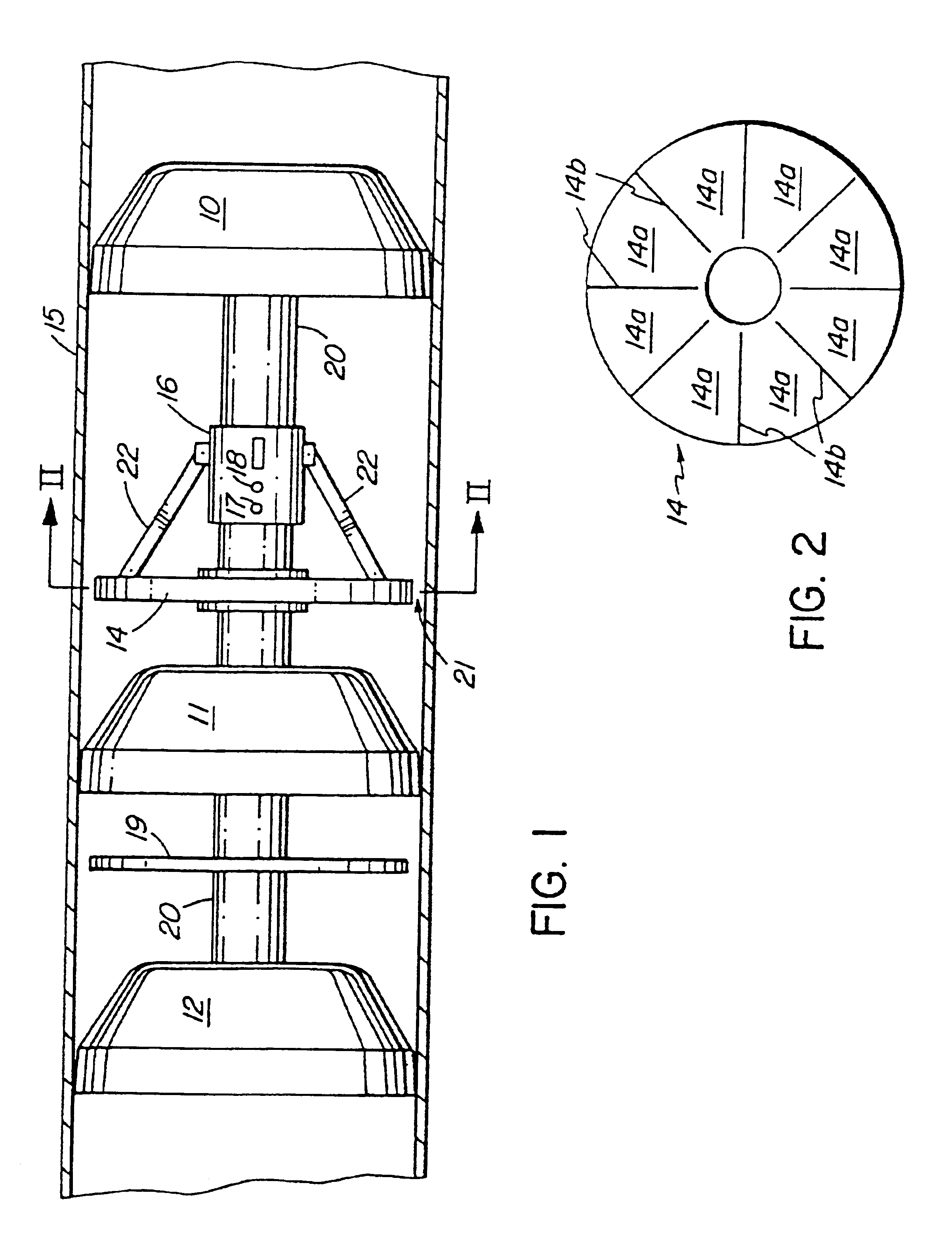
the inventive caliper pig is provided with supporting elastomeric rings 10, 11, 12 connected to a centrally disposed cylindric body one after the other and comprised of a front ring 10, an intermediate ring 11 and a rear ring at the back end of the pig.

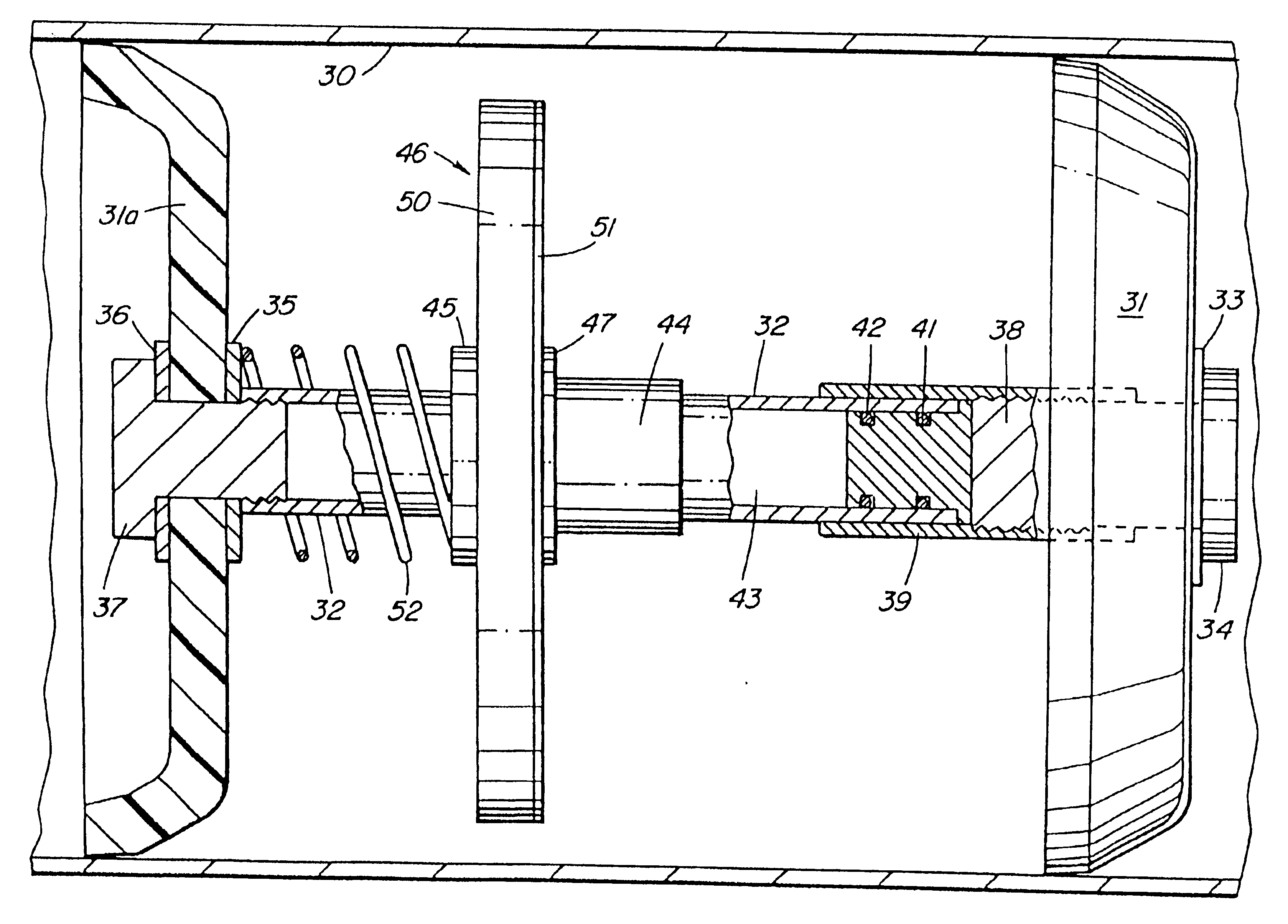
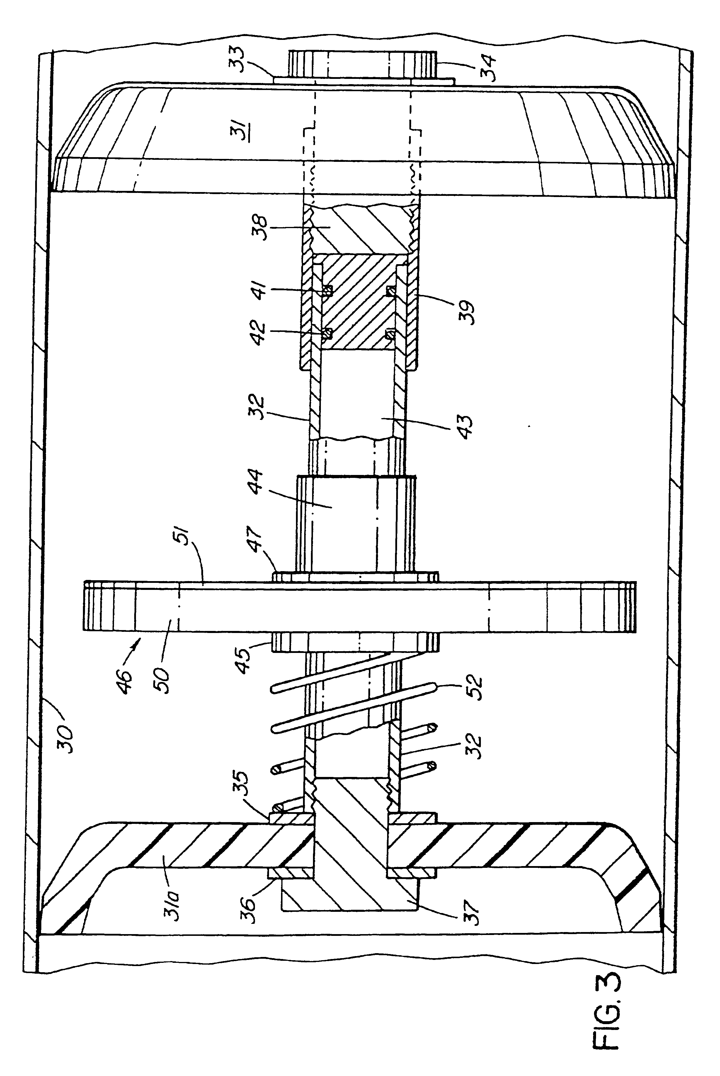
A segmented, generally disk-shaped resilient member has a number of segments separated from each other along a generally radial line of separation 14b. The member 14 is concentric with the support or guide rings 10-12. It is fixedly secured to the body 20 between the front support ring 10 and the intermediate support or guide ring 11. The resilient member 14 has a smaller outside diameter than the inside diameter of the pipeline 15. The member 14 thus defines an annular void between its outer surface and the inner surface of the pipeline wall. The member 14 may be provided with a scratch recording leading face not shown in FIGS. 1 and 2 but described later with reference to FIGS. 3 and 4.

The radial width of the void 21 is predetermine...


PUM


Abstract

An obstacle detecting pig for preliminary inspection of a section of a pipeline travels through the section and determines if there are any restrictions that exceed industry guidelines or that might damage other pigs that require the full bore of the pipe. In a first embodiment, a disk-shaped segmented resilient member (14) is mounted in the body of the pig. Its outside diameter is smaller by a spacing (21) than the inside diameter of the pipeline (15). The spacing is set at the maximum tolerable size of the obstacle encountered. The deformation of the member (14) is transmitted by a linkage (22) to a slider (16) activating a switch system signaling that an obstacle has been encountered. A non-resiliently deformable checkup disk (19) may be provided at the rear end of the pig, to double check that a no-signal passage through the pipe is not due to failure of the switching system. In a particularly preferred embodiment, the resilient member is a disc-shaped detector (46) made from an elastomer and provided at its leading surface with a scratch recording layer (51), for instance a layer of lead which is thin enough to follow resilient deformations of the elastomeric ring (50) as it encounters an obstacle, and return of the ring back to its regular, shape. The scratches caused on the recording layer are evaluated after the passage of the pig through the examined pipeline section. The detector is mounted directly on a slider (44) or the like operating device designed to produce electric signal when an anomaly is encountered. Preferably, the detector (46) is a replaceable element of the pig.The device is structurally simple thus providing low manufacturing and operation costs and simple operation.

Description

BACKGROUND OF THE INVENTIONThe present invention relates to an obstacle monitoring pipeline pig used in checking the interior of a pipeline for obstacles which might impede the movement of subsequently used pipeline inspecting devices or which exceed industry guidelines.A number of caliper pigs are on the market that provide detection of anomalies inside pipelines. They are usually expensive to produce and operate. These existing pigs monitor all restrictions along a pipeline regardless of the size of the anomalies. They normally collect a significant amount of data that requires interpretation by a technician or computer programs. This type of caliper pigs is represented, for instance, by the disclosure of U.S. Pat. Nos. 4,953,412 and 5,088,336 (both Rosenberg et al.) and also by U.S. Pat. No. 3,755,908 (VerNooy). The disclosures of the above patents are incorporated herein by reference.U.S. Pat. No. 4,481,816 (Prentice) describes a caliper pig provided with a monitoring arrangemen...

Claims


Application Information

Patent Timeline
IPC IPC(8): F16L55/38F16L55/26
CPCF16L55/38
Inventor SAVARD, DONALD D.
Owner DONSA
Learn More