Lockwireless anti-rotation fitting

a technology of anti-rotation and locking wires, which is applied in the direction of adjustable joints, pipe joints, engine seals, etc., can solve the problems of not being as robust as conventional components and difficult to ensure the safety of connection wiring, and achieve the effect of robust and economical manufactur

Inactive Publication Date: 2005-02-22
PARKER INTANGIBLES LLC
View PDF24 Cites 78 Cited by
  • Summary
  • Abstract
  • Description
  • Claims
  • Application Information

AI Technical Summary

Benefits of technology

The present invention is directed, broadly, to lockwireless fittings. More particularly, the invention is directed to a lockwireless fitting construction, such as for tubing, which eliminates the need for a special adapter, and which is robust and economical to manufacture.

Problems solved by technology

In practice, the safety wiring of the connection can be difficult.
In this regard, the fittings which heretofore have constituted the state of the art typically must employ specially designed adapters and other components which may involve added expense, require special tools or steps for make-up, and / or may not be as robust as conventional componentry if dropped or otherwise subjected to rough handling.

Method used


Image

  • Lockwireless anti-rotation fitting
  • Lockwireless anti-rotation fitting
  • Lockwireless anti-rotation fitting

Examples


Embodiment Construction

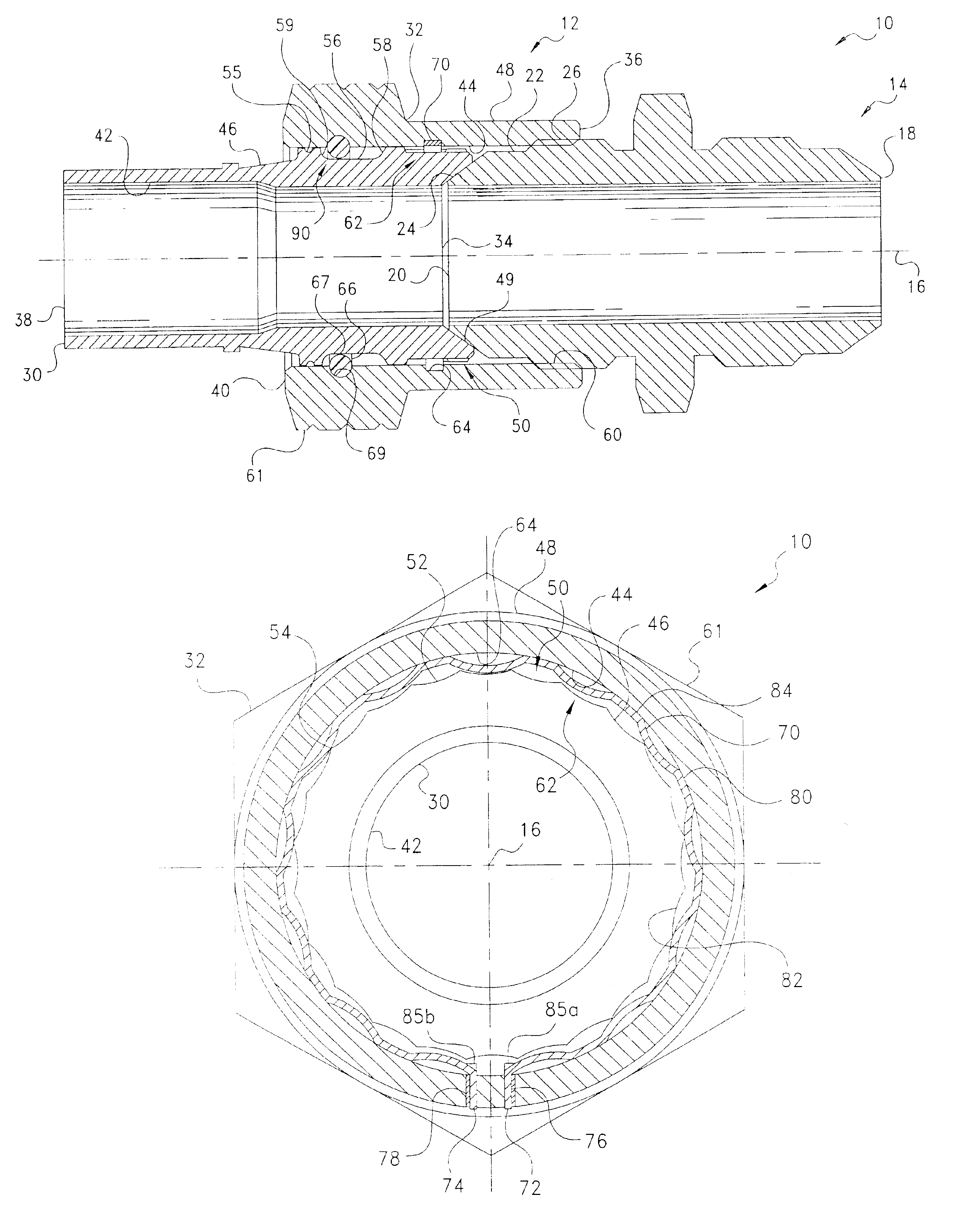
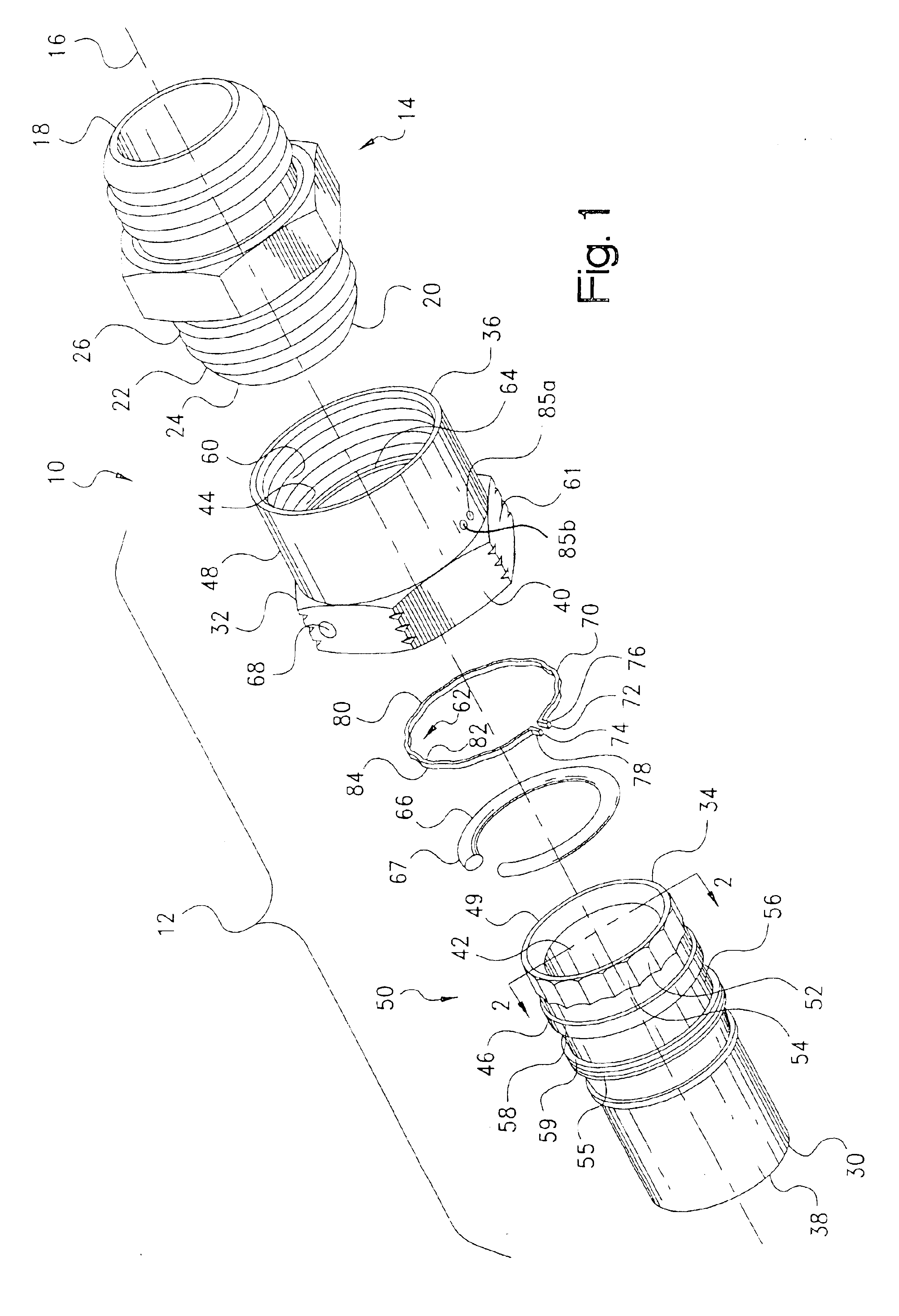
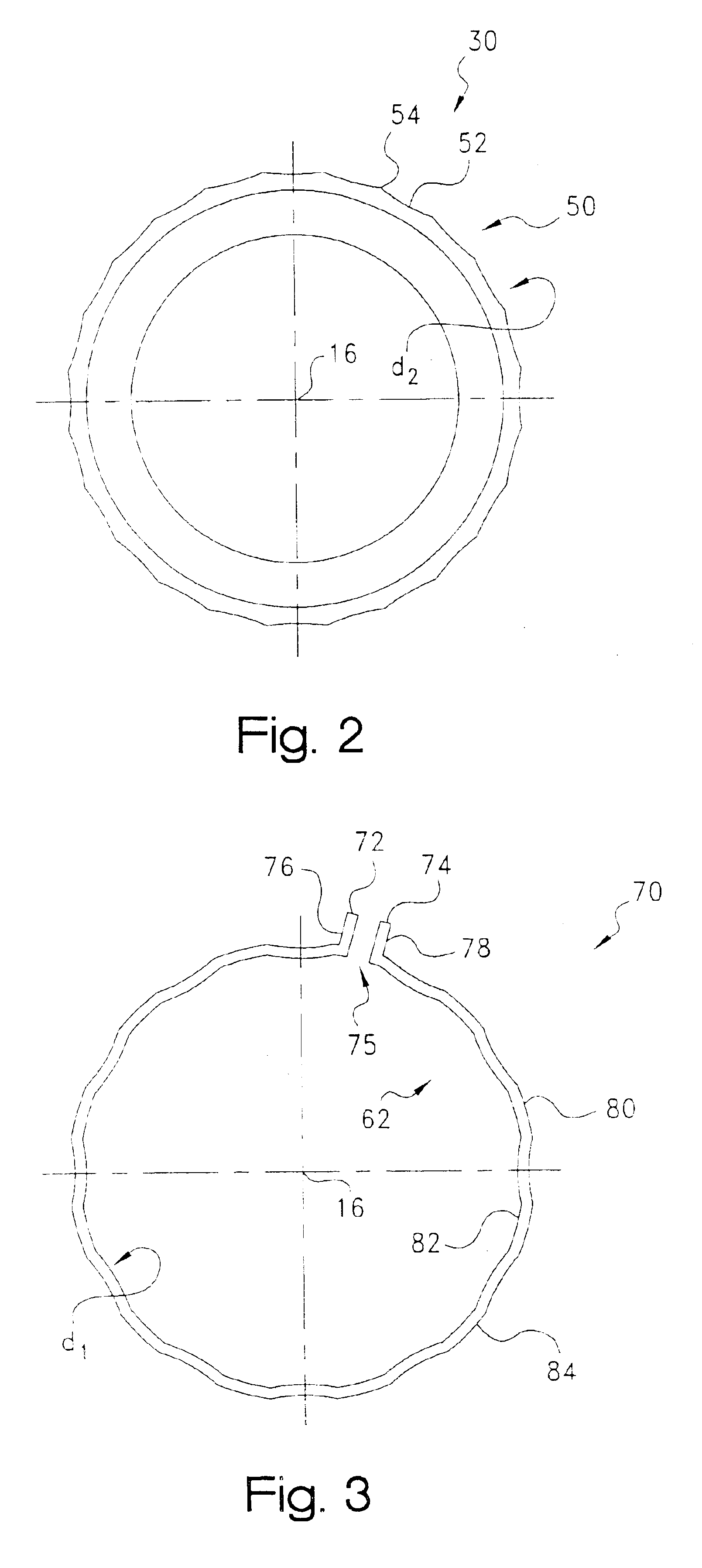
Certain terminology may be employed in the following description for convenience rather than for any limiting purpose. For example, the terms “forward” and “rearward,”“front” and “rear,”“right” and “left,”“upper” and “lower,”“top” and “bottom,” and “right” and “left” designate directions in the drawings to which reference is made, with the terms “inward,”“inner,”“interior,” or “inboard” and “outward,”“outer,”“exterior,” or “outboard” referring, respectively, to directions toward and away from the center of the referenced element, the terms “radial” or “vertical” and “axial” or “horizontal” referring, respectively, to directions or planes perpendicular and parallel to the longitudinal central axis of the referenced element. Terminology of similar import other than the words specifically mentioned above likewise is to be considered as being used for purposes of convenience rather than in any limiting sense.

In the figures, elements having an alphanumeric designation may be referenced h...


PUM


Abstract

A lockwireless, anti-rotation fitting for connection to a connector. The fitting includes a coupler having a series of circumferential engagement portions disposed about an outer peripheral surface, and a nut receivable coaxially over the outer peripheral surface of the coupler, and which is threadably engageable with the connector. The nut also has a series of complementary circumferential engagement portions disposed about at an inner peripheral surface. With the nut being received coaxially over the first outer peripheral surface of the coupler, the nut is threadably engageable with the connector urging the coupler into a sealing engagement with a sealing surface of the connector, and with the coupler being engaged with the connector sealing surface, the first and second engagement portions are interengaged to delimit the rotation of the nut relative to the connector.

Description

BACKGROUND OF THE INVENTIONThe present invention relates generally to compression-type fittings such as for coupling the end of a length of tubing to another member, and more particularly to such a fitting which is of an anti-rotation type and which may used as a replacement for conventional lock or safety wire fittings.Compression fittings are widely used in a variety of instrumentation, pneumatic, hydraulic, process, power, refrigeration, industrial, mobile, transportation, aerospace, military, and other fluid power or control applications utilizing plastic or metal tubing. Typically employing an internally or externally threaded nut and an associated ferrule, flare, or other tube end which is formed or provided to seal between the tubing and a complementary-threaded, relative to the nut, nipple, adapter, body, or other connector, these fittings have been adapted for use with many different tubing types including metals such as copper, brass, steel, stainless steel, titanium, alum...

Claims


Application Information

Patent Timeline
Patent Type & Authority Patents(United States)
IPC IPC(8): F16L19/00
CPCF16L19/005
Inventor VYSE, GERRARD N.STROEMPL, PETER J.
Owner PARKER INTANGIBLES LLC
Why Eureka
Try Eureka