Non-rotating wheel cover

Inactive Publication Date: 2005-02-22
AAI TECH
View PDF5 Cites 48 Cited by
  • Summary
  • Abstract
  • Description
  • Claims
  • Application Information

AI Technical Summary

Benefits of technology

The cover assembly can include at least one guide member located on the inside face of the wheel cover disk, the member cooperating with a corresponding guide member formed in the hub arm in a manner which ensures that the cover disk is fitted to the hub arm in only one position. The interior face of the wheel cover disk can include at least two guide protrusions which can fit into corresponding receptacles in the hub arm. The interior face of the wheel cover disk can include an asymmetrical group of guide protrusions which can fit into corresponding receptacles in the hub arm and ensure that the disk is installed in an upright position. The base plate can be connected to the hub arm by a shaft.
The cover assembly can include a pair of protrusions with holes therein which can fit within a corresponding

Problems solved by technology

However, such designs are usually overly complicated in structure, or do not in fact remain stationary

Method used


Image

  • Non-rotating wheel cover
  • Non-rotating wheel cover
  • Non-rotating wheel cover

Examples


Embodiment Construction

Throughout the following description, specific details are set forth in order to provide a more thorough understanding of the invention. However, the invention may be practiced without these particulars. In other instances, well known elements have not been shown or described in detail to avoid unnecessarily obscuring the invention. Accordingly, the specification and drawings are to be regarded in an illustrative, rather than a restrictive, sense.

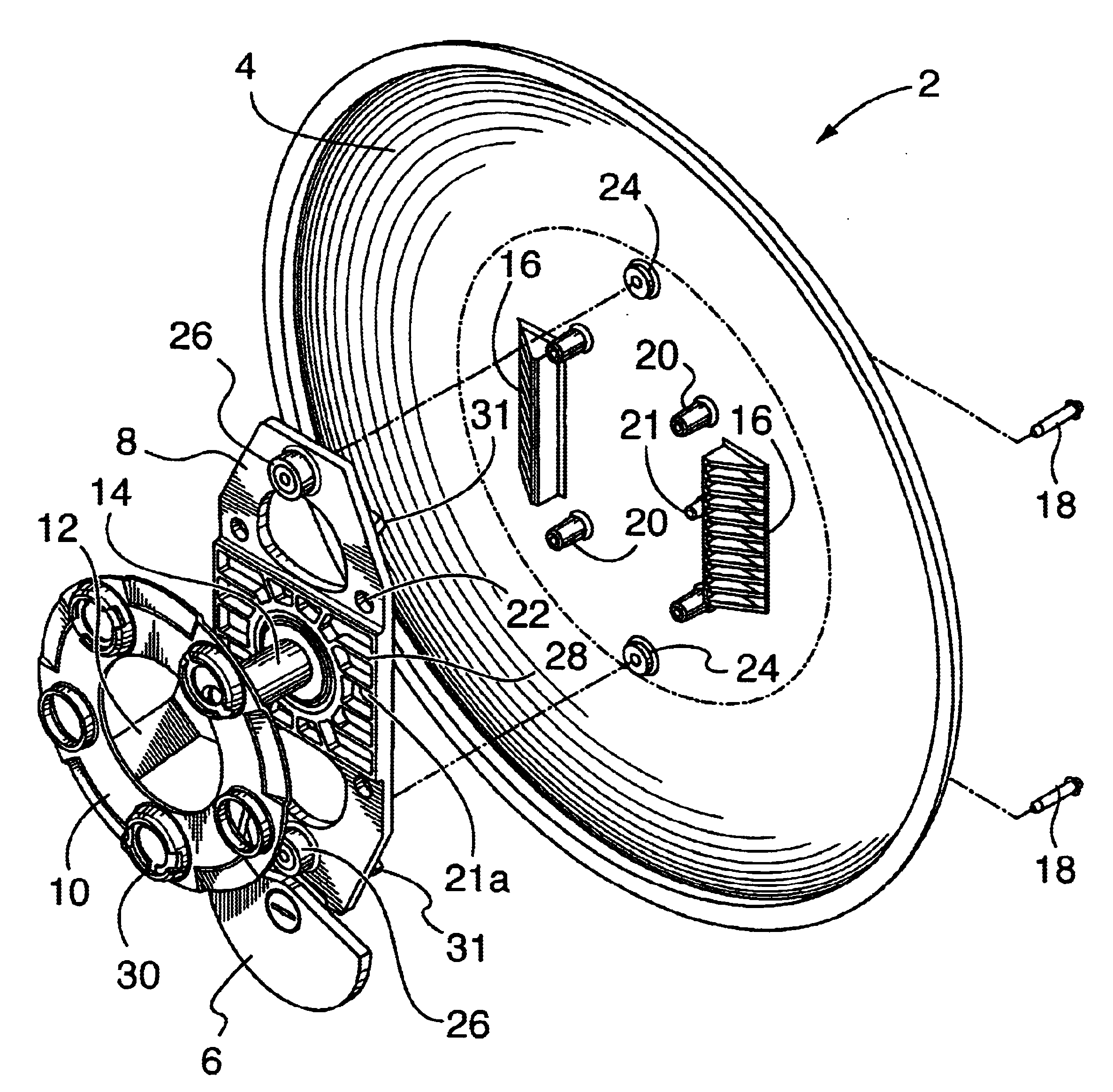
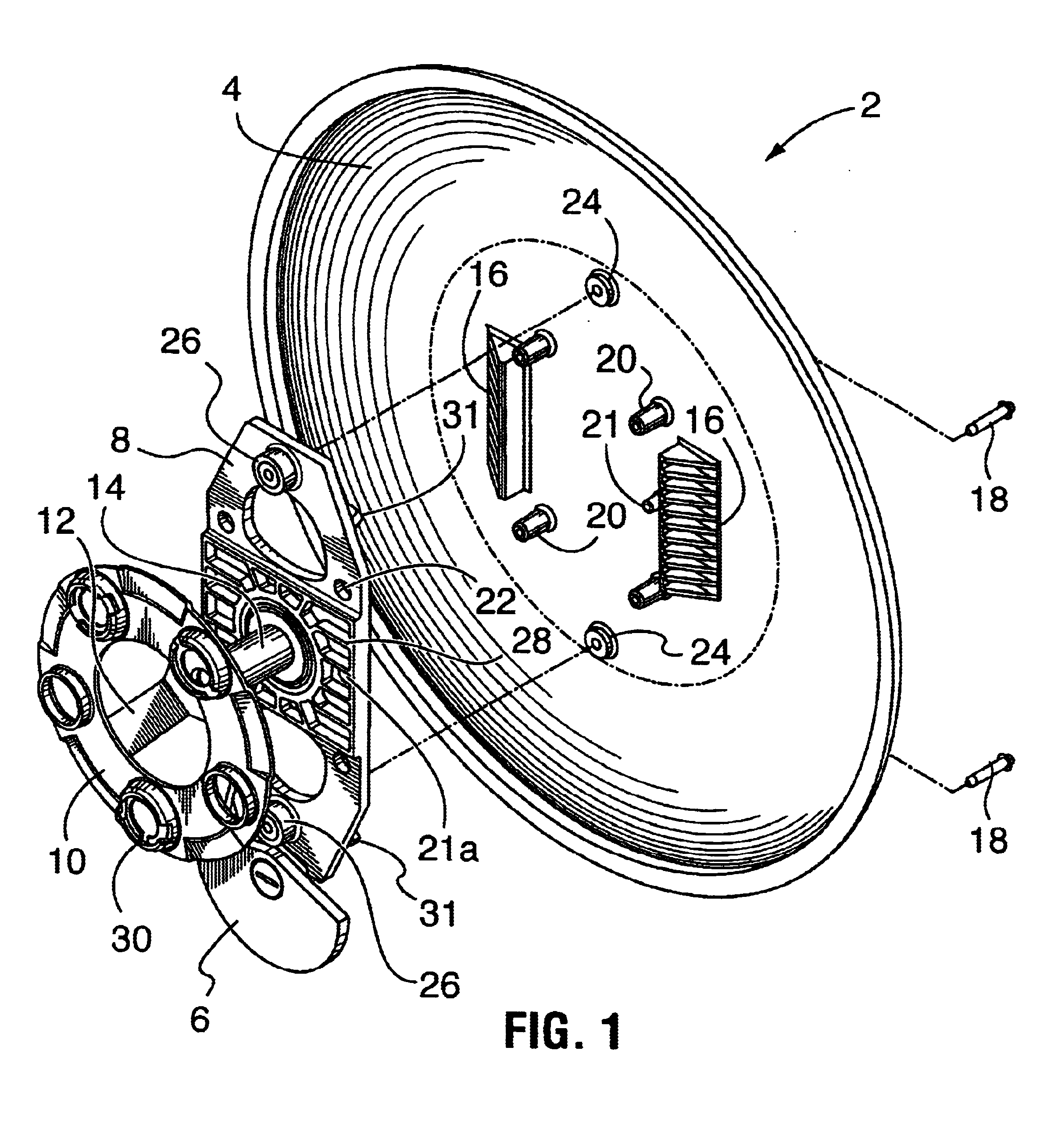
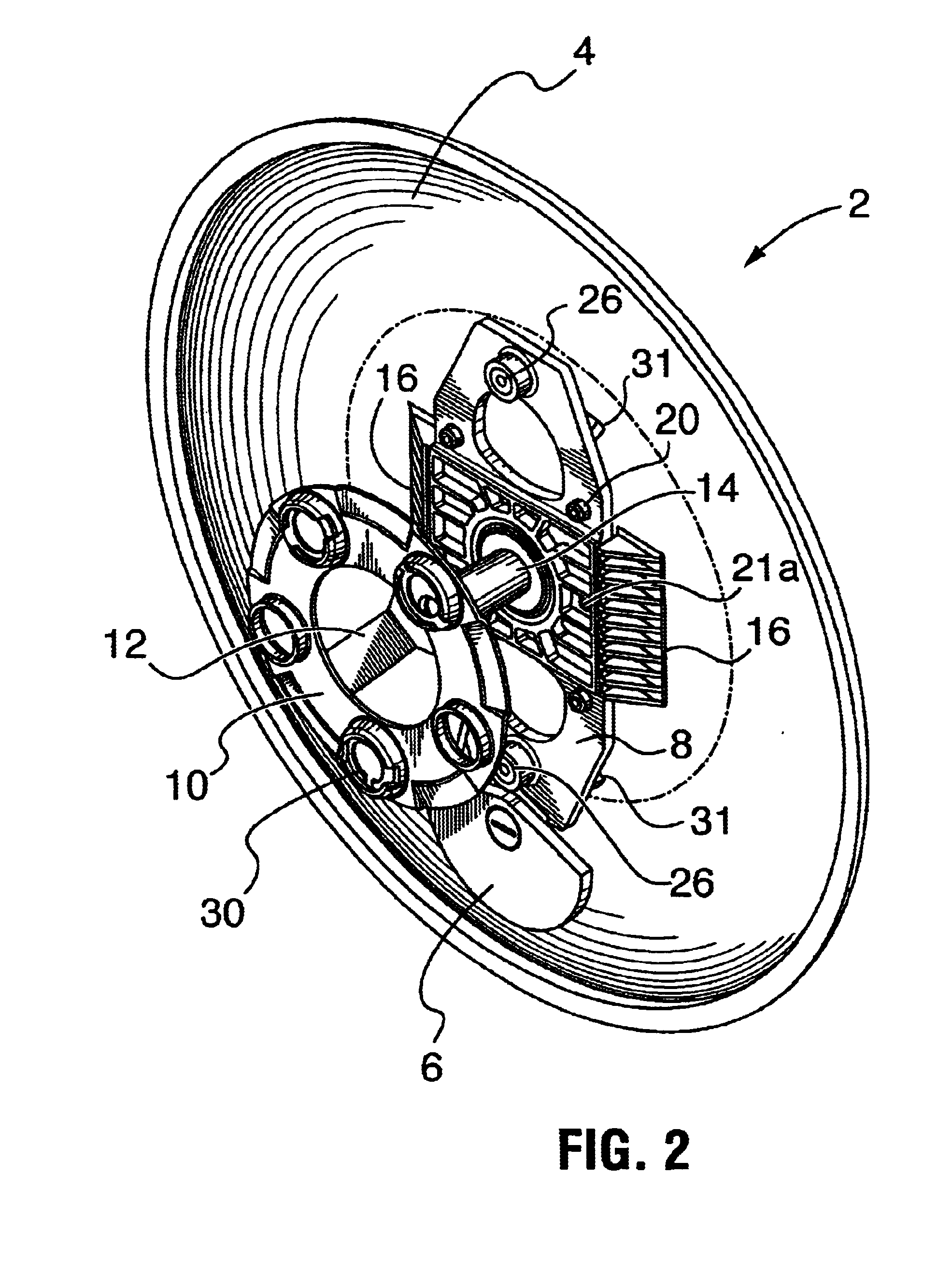
As seen in the drawings, FIG. 1 illustrates an isometric exploded view of the inside of a non-rotating wheel cover according to the invention. The wheel cover assembly 2 is constructed of a circular cover disk 4 which is intended to substantially cover the wheel rim area of the vehicle tire and rim assembly. The hub and wheel cover attachment assembly is constructed of a hub arm 8, which is connected by a bearing shaft 14 to a circular base plate 10 by means of a base connection 12. A weight 6 is either pivotally or fixedly connected to the...


PUM


Abstract

This invention relates to a novel non-rotating wheel cover for use with vehicle wheels. More particularly, this invention pertains to a wheel cover which fits over the central part of a vehicle wheel and remains stationary when the vehicle wheel is rotating. A wheel cover assembly comprising: (a) a wheel cover disk; (b) a hub arm which is removably attachable to the interior face of the wheel cover disk; (c) a weight which is connected to the base of the hub arm; (d) a base plate which has stud receiving holes formed therein, the base plate being rotatably connected to the hub arm.

Description

FIELD OF THE INVENTIONThis invention relates to a novel non-rotating wheel cover for use with vehicle wheels. More particularly, this invention pertains to a wheel cover which fits over the central hub of a vehicle wheel and does not rotate when the vehicle wheel is rotating.BACKGROUND OF THE INVENTIONA number of non-rotating wheel cover designs have been developed over the years. However, such designs are usually overly complicated in structure, or do not in fact remain stationary at various vehicle speeds, or are difficult to remove and reinstall when servicing the vehicle wheel.U.S. Pat. No. 6,045,195, granted Apr. 4, 2000, Okamoto, discloses a wheel cover which includes a fixable side fixture fixably mounted to the center of a wheel of a vehicle, so as to be able to position the cover to the central part thereof. A movable side fixture is pivotally mounted to the central part of the fixable side fixture through a bearing. A wheel cover body, substantially in the shape of a disc ...

Claims


Application Information

Patent Timeline
IPC IPC(8): B60B7/00B60B7/20
CPCB60B7/20
Inventor MCLEAN, BRUCE E.KLASSEN, IAN M.CONSTABLE, KEITH L.SMITH, STEPHEN
Owner AAI TECH
Why Eureka
Try Eureka