Micro-electromechanical fluid ejection device that utilizes rectilinear actuation
What is AI technical title?
AI technical title is built by Patsnap AI team. It summarizes the technical point description of the patent document.
a technology of rectilinear actuation and micro-electromechanical fluid, which is applied in the direction of printing, etc., can solve the problems of achieving a sufficient extent and speed of movemen
Inactive Publication Date: 2005-02-22
MEMJET TECH LTD +1
View PDF5 Cites 41 Cited by
Summary
Abstract
Description
Claims
Application Information
AI Technical Summary
This helps you quickly interpret patents by identifying the three key elements:
Problems solved by technology
Method used
Benefits of technology
Benefits of technology
an active nozzle chamber structure that has a roof wall that defines a fluid ejection port and an active wall that depends from the roof wall about the static wall, to define a remaining part of the nozzle chamber, the active structure being displaceable with respect to the static structure towards and away from the substrate respectively to reduce and increase a volume of the nozzle chamber so that fluid in the nozzle chamber is ejected from the fluid ejection port;
The sealing formation may include a re-entrant portion that opens towards the substrate and a lip that is positioned on the re-entrant portion to extend outwardly therefrom. The lip and a free edge of the active wall may be shaped and positioned with respect to each other so that when the nozzle chamber is filled with a liquid, the lip and said free edge define anchor points for a meniscus, so that the meniscus can define a fluidic seal to inhibit leakage of the liquid from the nozzle chamber during operation.
Each active fluid-ejecting structure and each static fluid-ejecting structure may be5 shaped so that, when fluid is received in the nozzle chamber, the fluid-ejecting structures and the fluid define a fluidic seal to inhibit fluid from leaking out of the nozzle chamber between the fluid-ejecting structures.
Problems solved by technology
As set out in the above referenced applications / patents, the Applicant has spent a substantial amount of time and effort in developing printheads that incorporate micro electro-mechanical system (MEMS)—based components to achieve the ejection of ink necessary for printing.
A particular difficulty with such a configuration is achieving a sufficient extent and speed of movement of the structure to achieve ink drop ejection.
Method used
Image
Click on the blue label to locate the original text in one second.
Reading with bidirectional positioning of images and text.
Examples
Embodiment Construction
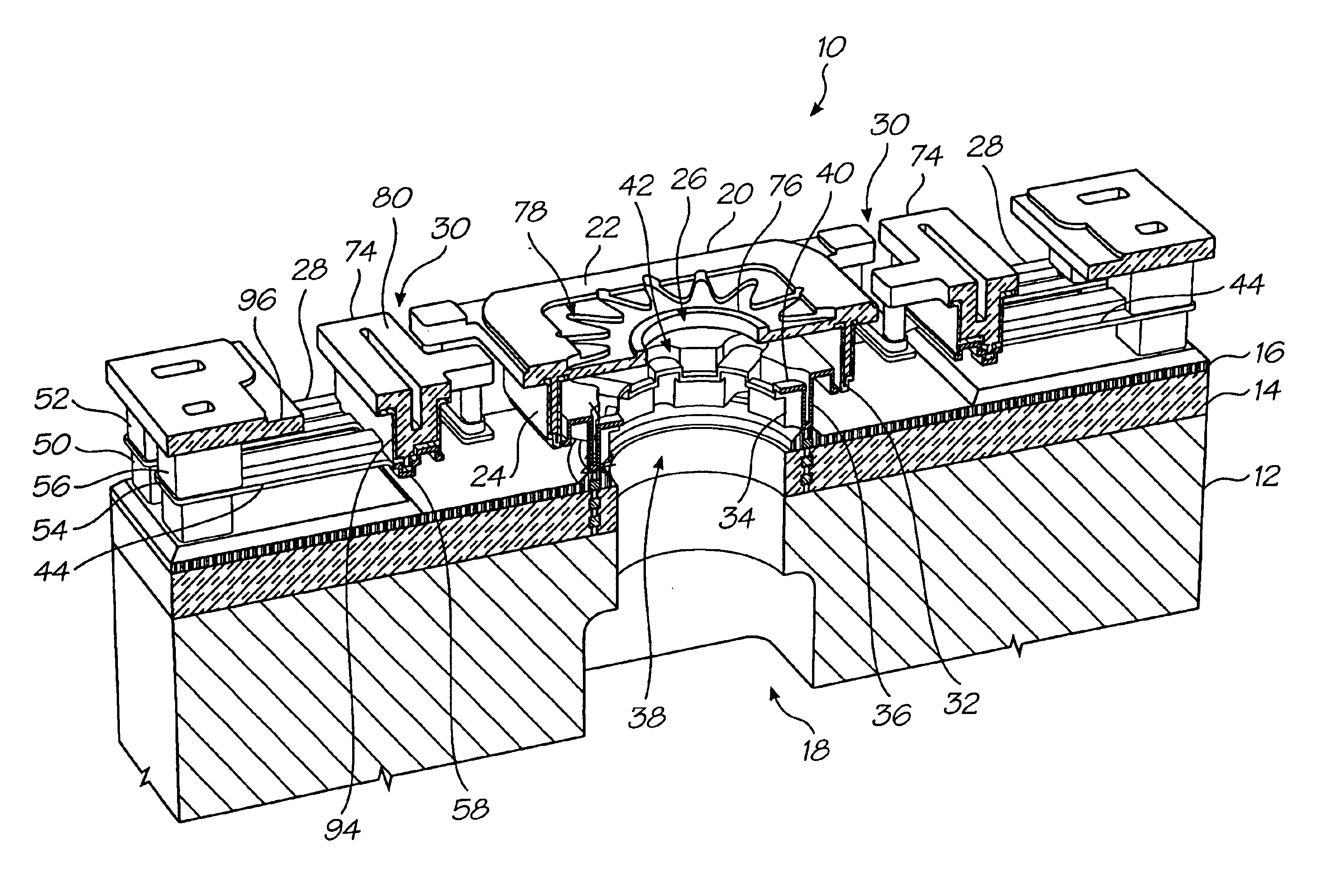
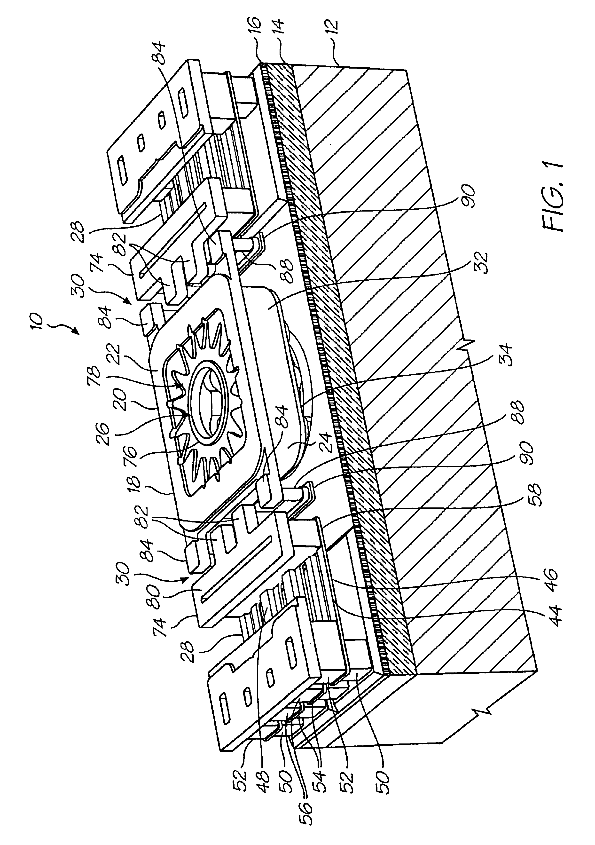
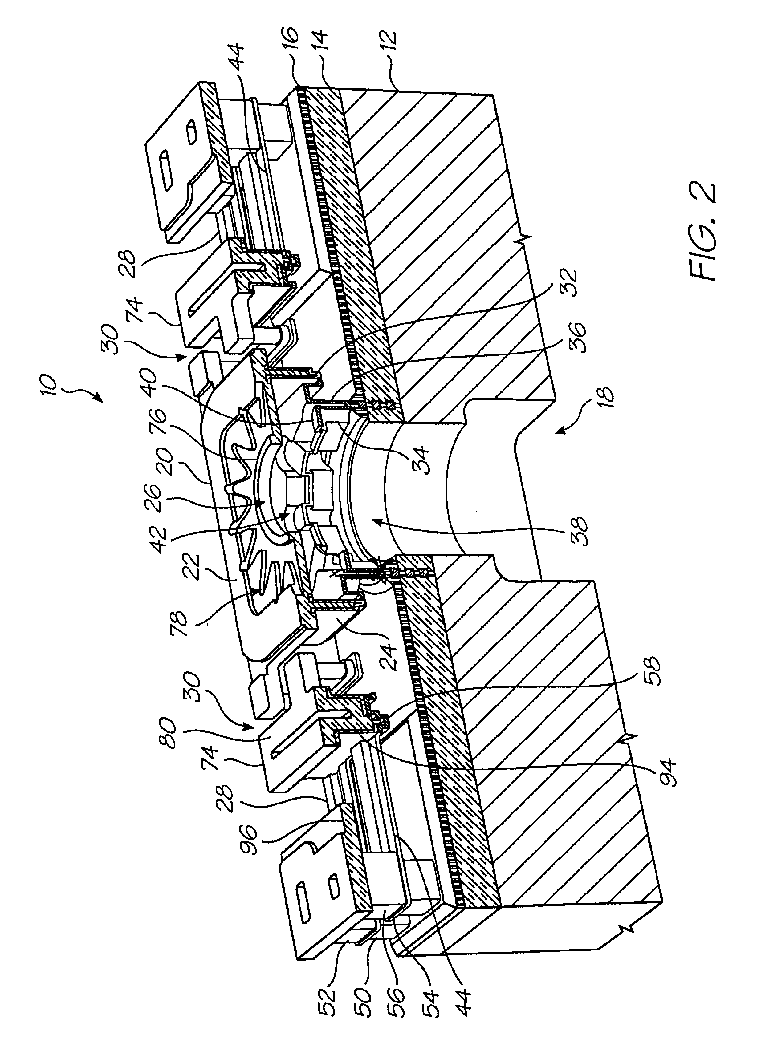
In FIGS. 1 to 5, reference numeral 10 generally indicates a nozzle arrangement of a printhead chip, in accordance with the invention, for an ink jet printhead.
The nozzle arrangement 10 is one of a plurality of such nozzle arrangements formed on a siliconwafer substrate 12 to define the printhead chip of the invention. As set out in the background of this specification, a single printhead can contain up to 84 000 such nozzle arrangements. For the purposes of clarity and ease of description, only one nozzle arrangement is described. It is to be appreciated that a person of ordinary skill in the field can readily obtain the printhead chip by simply replicating the nozzle arrangement 10 on the wafer substrate 12.
The printhead chip is the product of an integrated circuit fabrication technique. In particular, each nozzle arrangement 10 is the product of a MEMS—based fabrication technique. As is known, such a fabrication technique involves the deposition of functional layers and sacrifici...
PUM
Abstract
A micro-electromechanical fluid ejection device includes a substrate that incorporates drive circuitry. A fluid inlet channel is defined through the substrate. A static nozzle chamber structure is positioned on the substrate to extend from the substrate and defines a static wall that bounds the fluid inlet channel to form part of a nozzle chamber. An active nozzle chamber structure has a roof wall that defines a fluid ejection port and an active wall that depends from the roof wall about the static wall to define a remaining part of the nozzle chamber. The active structure is displaceable with respect to the static structure towards and away from the substrate respectively to reduce and increase a volume of the nozzle chamber so that fluid in the nozzle chamber is ejected from the fluid ejection port. A fluid displacement member is positioned on the static wall to define a fluid displacement area that faces the roof wall to facilitate ejection of fluid from the fluid ejection port. At least two actuators are connected to the drive circuitry and are operatively arranged with respect to the active structure to displace the active structure towards and away from the substrate on receipt of an actuating electrical signal from the drive circuitry. A coupling structure is interposed between each actuator and the active structure. The coupling structures are configured and connected to the active structure to impart substantially rectilinear movement to the active structure on operation of the actuators.
Description
STATEMENT REGARDING FEDERALLY SPONSORED RESEARCH OR DEVELOPMENTNot ApplicableFIELD OF THE INVENTIONThis invention relates to a micro-electromechanical fluid ejection device.REFERENCED PATENT APPLICATIONSThe following applications are incorporated by reference:6,227,6526,213,5886,213,5896,231,1636,247,79509 / 113,0996,244,6916,257,70409 / 112,7786,220,6946,257,7056,247,7946,234,6106,247,7936,264,3066,241,3426,247,7926,264,3076,254,2206,234,61109 / 112,80809 / 112,8096,239,82109 / 113,0836,247,79609 / 113,12209 / 112,79309 / 112,79409 / 113,12809 / 113,1276,227,6536,234,6096,238,0406,188,4156,227,6546,209,9896,247,79109 / 112,7646,217,15309 / 112,7676,243,11309 / 112,8076,247,7906,260,9536,267,46909 / 425,41909 / 425,41809 / 425,19409 / 425,19309 / 422,89209 / 422,80609 / 425,42009 / 422,89309 / 693,70309 / 693,70609 / 693,31309 / 693,27909 / 693,72709 / 693,70809 / 575,14109 / 113,053BACKGROUND OF THE INVENTIONAs set out in the above referenced applications / patents, the Applicant has spent a substantial amount of time and effort in developi...
Claims
Application Information
Patent Timeline
Application Date:The date an application was filed.
Publication Date:The date a patent or application was officially published.
First Publication Date:The earliest publication date of a patent with the same application number.
Issue Date:Publication date of the patent grant document.
PCT Entry Date:The Entry date of PCT National Phase.
Estimated Expiry Date:The statutory expiry date of a patent right according to the Patent Law, and it is the longest term of protection that the patent right can achieve without the termination of the patent right due to other reasons(Term extension factor has been taken into account ).
Invalid Date:Actual expiry date is based on effective date or publication date of legal transaction data of invalid patent.

