
Tunable power amplifier matching circuit

a power amplifier and matching circuit technology, applied in the direction of waveguide horns, diodes, discontnuous tuning with seperate pretuned circuits, etc., can solve the problems of significant portion of the cost, size and power consumption of wireless communication devices, and the significant portion of the cost, size and power consumption of the transceiver, so as to reduce the cost, size and power consumption

Inactive Publication Date: 2005-02-22
KYOCERA CORP
View PDF59 Cites 148 Cited by
  • Summary
  • Abstract
  • Description
  • Claims
  • Application Information

AI Technical Summary

Benefits of technology

The present invention provides a way to reduce the cost, size, and power consumption of wireless communication devices by integrating components like antennas, duplexers, diplexers, isolators, and power amplifiers onto one substrate. This is done by placing each component, with the appropriate matching circuit, directly onto the substrate or by direct fabrication of the component and matching circuit onto the substrate. By doing this, the components can be more efficiently utilized, reducing the overall cost and size of the wireless communication device. The invention also integrates a ferro-electric tunable duplexer onto the substrate, which can further reduce the cost, size, and power consumption of the wireless communication device. The matching circuits for the components can be patterned or placed on the substrate, and the isolator and duplexer can be fabricated directly onto the substrate or mounted as discrete components. The topology of the matching circuits can be typical, with the exception of the antenna matching circuit, which uses L-C ladders to create a higher order matching circuit. Overall, the invention provides a more efficient and cost-effective way to integrate components in wireless communication devices.

Problems solved by technology

Transceivers account for a significant portion of the cost, size and power consumption of wireless communication devices.
The front end, including antennas, duplexers, diplexers, isolators, PA's, LNA's and their matching circuits accounts for a significant portion of the cost, size and power consumption of the transceiver.

Method used


Image

  • Tunable power amplifier matching circuit
  • Tunable power amplifier matching circuit
  • Tunable power amplifier matching circuit

Examples


Embodiment Construction

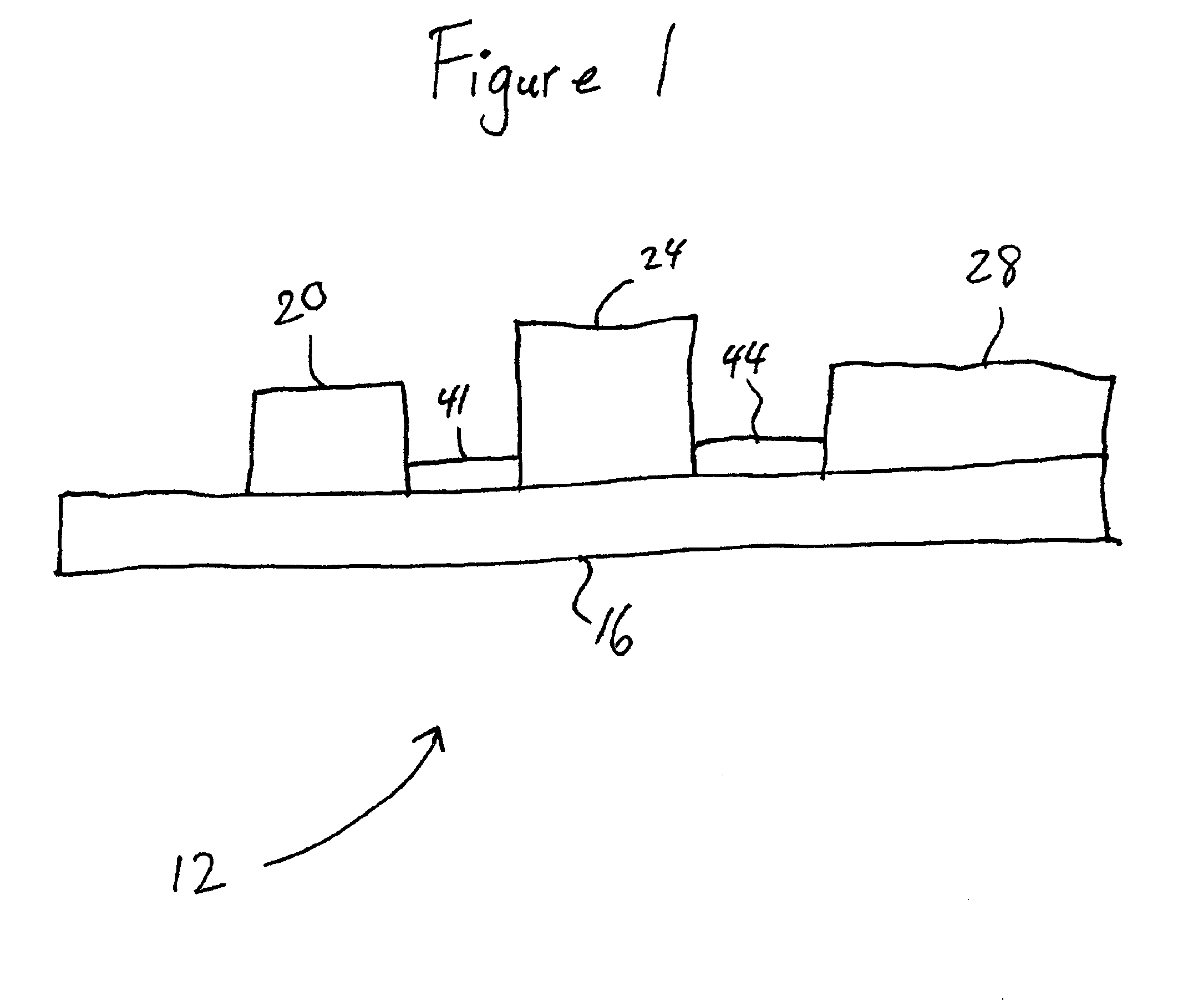
Referring now to FIG. 1, an integrated antenna interface unit (AIU) 12 is shown. While a duplexer is shown, as is common in a CDMA handset, a multiplexer could be used as well. While the description that follows specifies a duplexer throughout, it is to be understood that a multiplexer or BPF could be substituted for the duplexer. A PA unit 20, an isolator unit 24, and a duplexer 28 are all attached to a common substrate 16, eliminating the need for individual substrates for each of these components.

The substrate is preferably made of a carefully selected material. The substrate parameters that are typically critical are dielectric constant, loss tangent, thermal properties, cost and ease of processing. Typically, a dielectric constant should be less than about 40, and the loss tangent should be less than about 0.001 in the frequency range of interest. A low loss substrate may be more expensive than a higher loss substrate. A designer must frequently balance the issues of cost and p...


PUM

PropertyMeasurementUnit
output impedancesaaaaaaaaaa
impedanceaaaaaaaaaa
impedancesaaaaaaaaaa

Abstract

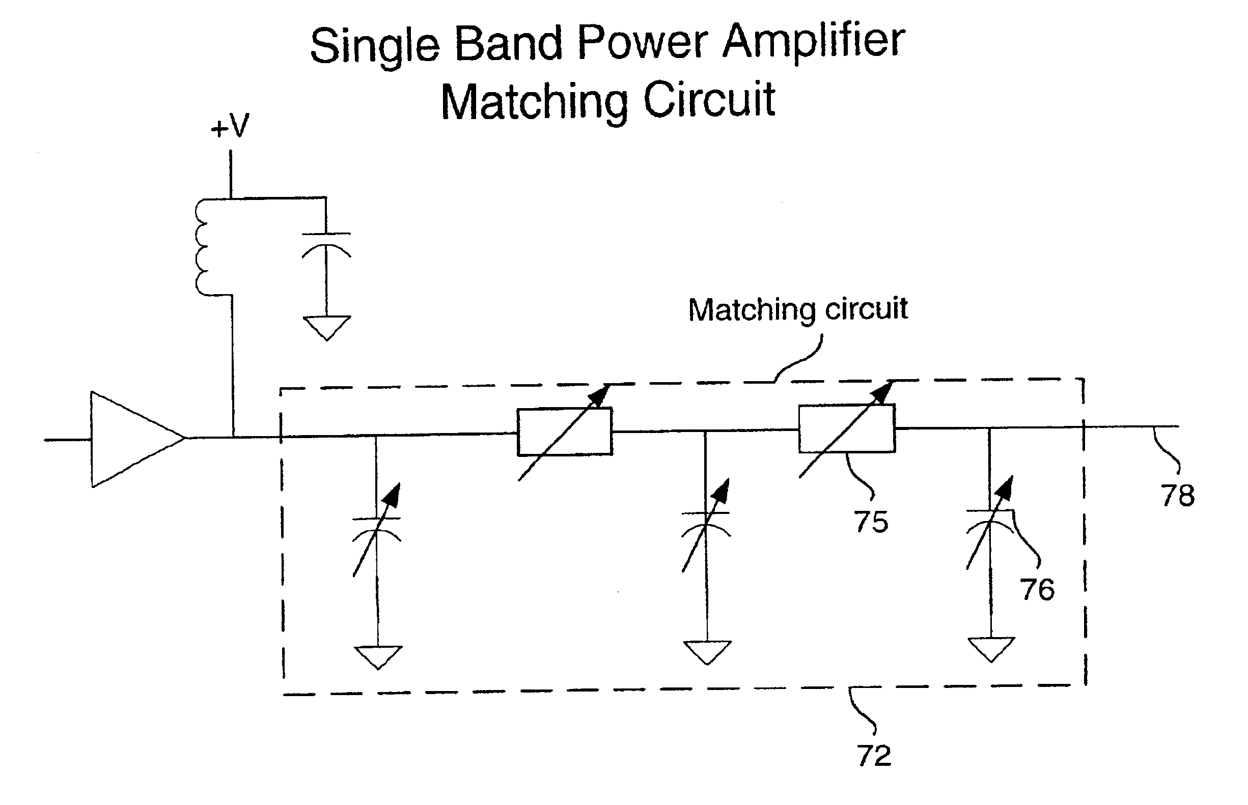
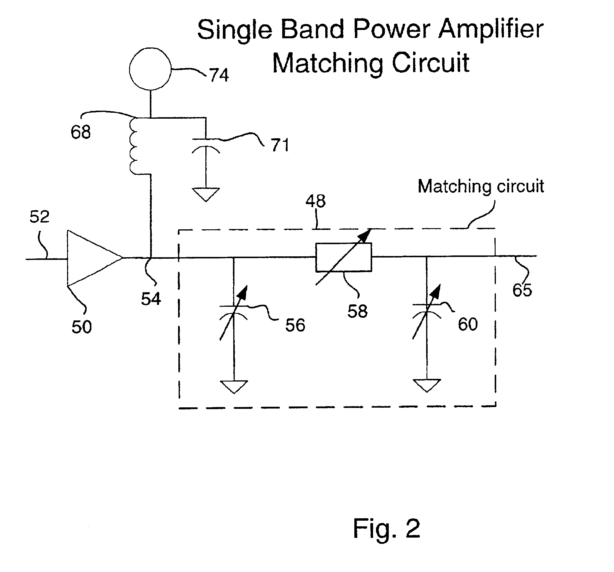
A power amplifier matching circuit is provided. The matching circuit includes a ferro-electric tunable component. A control signal is applied to the tunable component, changing the component's impedance. This changes the impedance of the matching circuit.

Description

BACKGROUNDWireless communication devices, such as, but not limited to, wireless telephones, use many electronic components to transmit and receive signals over the air. A transceiver is the part of a wireless telephone that actually sends and receives signals. The front end of a transceiver is the portion of a transceiver closest to the air interface in the signal path. The front end includes an antenna and several components near the antenna in the signal path. Several of the components required in the front end of the transceiver are power amplifiers (PA's), isolators, low noise amplifiers (LNA's) and multiplexers. Each of these components are typically manufactured as packaged devices. In the case of a PA or an LNA, this package typically includes the active device and internal input and output matching circuits for bringing the input and output resistances up to an industry standard 50 ohms.In one common embodiment, the packaged PA is comprised of a high performance FET (e.g., G...

Claims


Application Information

Patent Timeline
Patent Type & Authority Patents(United States)
IPC IPC(8): H01G7/00H01G7/06H01P5/04H01Q13/00H01P1/213H01Q9/04H01Q9/28H01P1/203H01Q1/00H03B5/36H01Q13/20H01Q3/44H01Q9/16H01P1/20H01Q13/06H01Q13/02H01Q9/30H03H7/20H03F1/00H03F3/191H03H7/00H03L1/02H03F3/189H01Q3/00H03L1/00H04B1/30H03J5/24H03F1/56H03J5/00H03L7/18H03L7/16H03B5/18H03H7/01H03H7/12H01G4/12G01R27/26H01G4/33H01G4/40H01L27/08H01P1/205H01P1/36H01P7/08H01Q1/24H01Q1/38H01Q9/14H01Q9/42H01Q13/08H01Q13/22H03B5/04H03B5/08H03B5/12H03H7/38H04B1/04H04B1/40H04L27/38
CPCG01R27/2694H01L27/0808H01P1/203H01P1/20336H01P1/20363H01P1/20381H01P1/2039H01P1/2056H01P1/213H01P5/04H03B5/04H03B5/1841H03B5/362H03F1/56H03F3/191H03H7/20H03J5/246H03L1/022H03L7/18H04B1/0458H04B1/30H03B5/124H03B5/1293H03B5/1262H04B1/40H01G7/06H03F2200/111H03F2200/294H03F2200/372H03H7/0123H03H7/12H04B1/0053H01Q9/04
Inventor TONCICH, STANLEY S.FORRESTER, TIM
Owner KYOCERA CORP
Learn More