Vehicle situation alert system with eye gaze controlled alert signal generation

a technology of situation alert and vehicle, which is applied in the direction of instruments, analogue processes, and specific applications using reradiation, etc., can solve the problems of collision, inability to see another vehicle, and inability of the vehicle operator to become awar

Inactive Publication Date: 2005-02-22
APTIV TECH LTD
View PDF26 Cites 112 Cited by
  • Summary
  • Abstract
  • Description
  • Claims
  • Application Information

AI Technical Summary

Benefits of technology

In yet another specific example, the vehicle may be equipped with an additional system to alert an operator that he is closer than a specified range of a leading vehicle based on a mathematical algorithm processing measured dynamic parameters of the vehicles. The additional system may determine the specified rang...

Problems solved by technology

Vehicle operators routinely encounter vehicle situations in which a decision is required or advisable to take action, either by performing a vehicle control action or by refraining from performing an intended vehicle control action, in order to avoid an undesirable event; but a vehicle operator may not become aware of such a situation in time for the optimal action.
But if the operator of the first vehicle is intending to change lanes into that occupied by the overtaking second vehicle, a collision might occur when that action is taken.
But most vehicles have a “blind spot,” in which another vehicle cannot be easily seen with such a mirror check.
But most o...

Method used


Image

  • Vehicle situation alert system with eye gaze controlled alert signal generation
  • Vehicle situation alert system with eye gaze controlled alert signal generation
  • Vehicle situation alert system with eye gaze controlled alert signal generation

Examples


Embodiment Construction

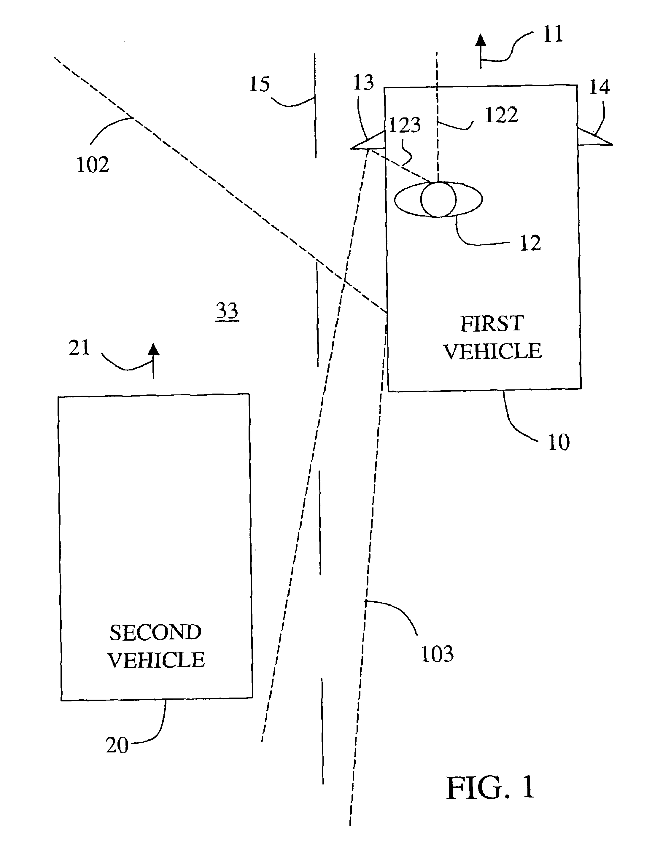
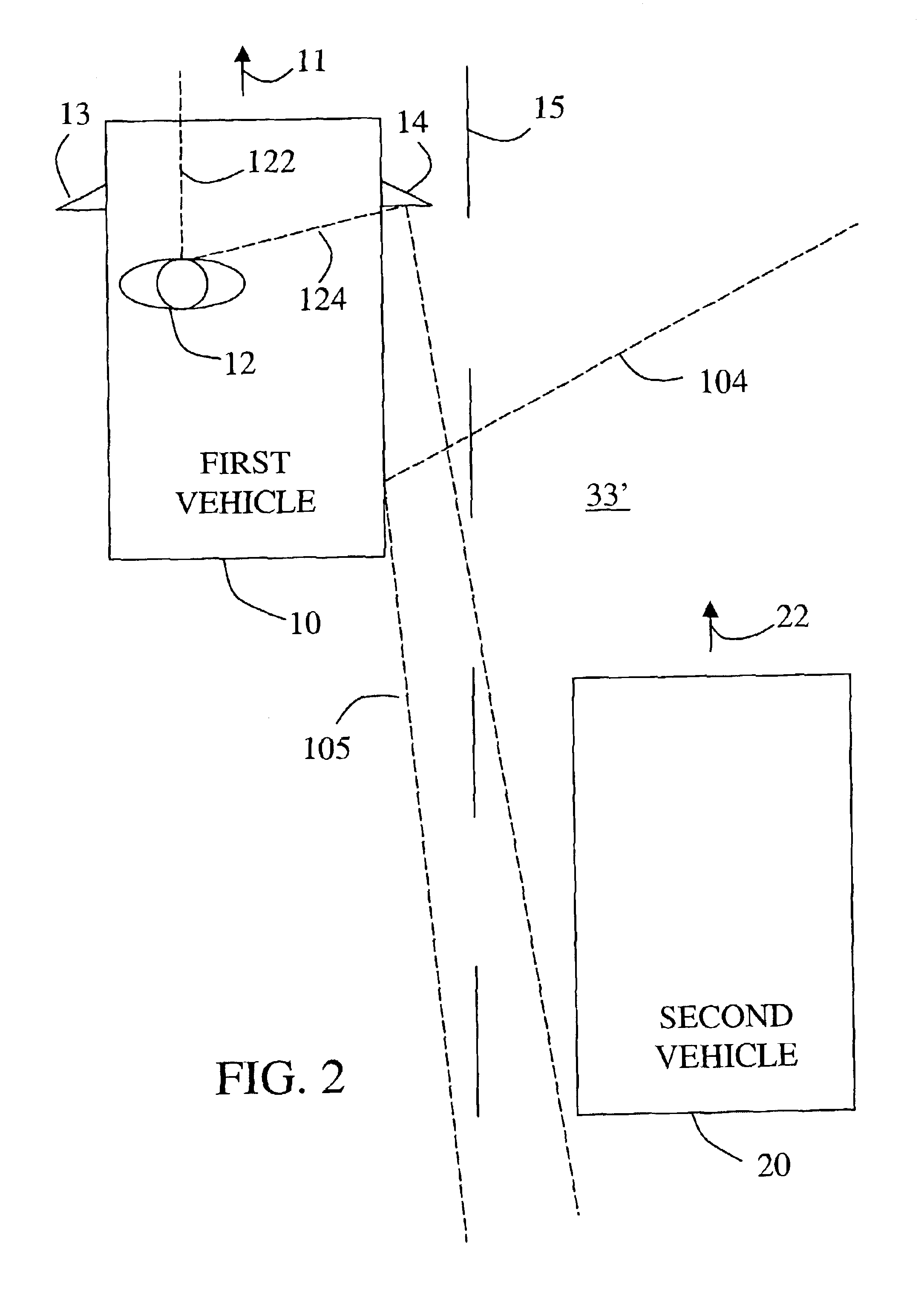
FIG. 1 shows a first vehicle 10 having a preferred embodiment of the apparatus of this invention and proceeding forward in the right hand one of two adjacent lanes separated by lane markers 15. First vehicle 10 is proceeding upward on the page, as indicated by arrow 11. An operator 12 is sitting on the driver side (the left side in this embodiment) of vehicle 10. Vehicle 10 is provided with an external, driver side rear view mirror 13 and may also be provided with an external, passenger side rear view mirror 14 (the passenger side is the side of the vehicle opposite the driver side).

A second vehicle 20 is somewhat behind the first vehicle 10 in the adjacent left hand lane and proceeding in the same direction, as indicated by arrow 21. Vehicle 20 has a high probability of being visible to operator 12 of vehicle 10 in the mirror 13 if his eye gaze direction is to the mirror, as indicated by dashed line 123; but it will not be visible to him if his eye gaze direction is directly to the...


PUM


Abstract

A system responds to detection of a vehicle situation by comparing a sensed eye gaze direction of the vehicle operator with data stored in memory. The stored data defines a first predetermined vehicle operator eye gaze direction indicating a high probability of operator desire that an alert signal be given and a second predetermined vehicle operator eye gaze direction indicating a low probability of operator desire that an alert signal be given. On the basis of the comparison, a first or second alert action is selected and an alert apparatus controlled accordingly. For example, the alternative alert actions may include (1) generating an alert signal versus not generating the alert signal, (2) generating an alert signal in a first manner versus generating an alert signal in a second manner, or (3) selecting a first value versus selecting a second value for a parameter in a mathematical control algorithm to determine when or whether to generate an alert signal.

Description

TECHNICAL FIELDThe technical field of this invention is vehicle situation alert systems.BACKGROUND OF THE INVENTIONVehicle operators routinely encounter vehicle situations in which a decision is required or advisable to take action, either by performing a vehicle control action or by refraining from performing an intended vehicle control action, in order to avoid an undesirable event; but a vehicle operator may not become aware of such a situation in time for the optimal action.For example, an operator of a first vehicle may be driving in a lane of a multi-lane roadway when a second, faster moving vehicle in an adjacent lane approaches from the rear. This does not by itself require any action by the first vehicle operator, as long as the operator is not planning to change lanes into the lane occupied by the overtaking second vehicle. But if the operator of the first vehicle is intending to change lanes into that occupied by the overtaking second vehicle, a collision might occur when...

Claims


Application Information

Patent Timeline
IPC IPC(8): B60Q1/50B60Q1/52G08G1/16G01S13/00G01S13/93G01S13/931
CPCB60Q9/008G08G1/16G01S13/931G01S2013/9332G01S2013/9357G08G1/166G01S2013/9322G01S2013/9315
Inventor NEWMAN, TIMOTHY J.SCHARENBROCH, GREGORY K.SMITH, MATTHEW R.ZHANG, HARRYWIDMANN, GLENN RWITT, GERALD J.
Owner APTIV TECH LTD
Why Eureka
Try Eureka