
Method, apparatus and system for reducing gain ripple in a raman-amplified WDM system

a raman-pumped wdm and gain ripple technology, applied in the field of optical communication, can solve the problems of limited and not very broad edfas, distortion of signal, and inability to use the gain bandwidth of the optical amplifier currently used, and achieve the effect of reducing gain rippl

Inactive Publication Date: 2005-02-22
WSOU INVESTMENTS LLC +1
View PDF12 Cites 11 Cited by
  • Summary
  • Abstract
  • Description
  • Claims
  • Application Information

AI Technical Summary

Benefits of technology

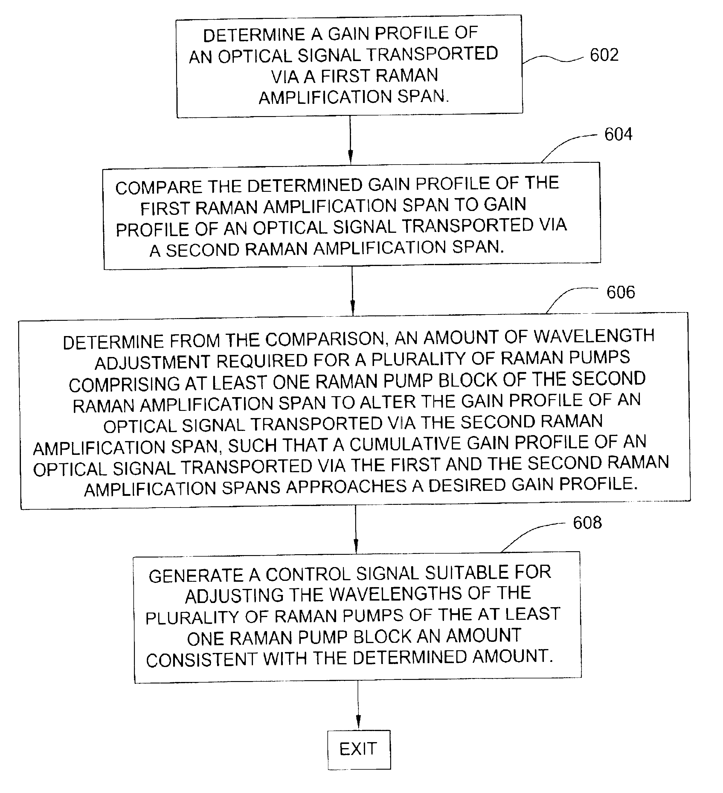
[0008]In one embodiment of the present invention, a method for reducing gain ripple in a Raman-amplified WDM system includes determining a gain profile of an optical signal transported via a first Raman amplification span in a Raman-amplified WDM system, comparing the determined gain profile to a gain profile of an optical signal transported via a second Raman amplification span, determining, from the comparison, an amount of wavelength adjustment required for a plurality of Raman pumps comprising at least one Raman pump block of the second Raman amplification span to alter the gain profile of an optical signal transported via the second Raman amplification span, such that a cumulative gain profile of an optical signal transported via the first and the second Raman amplification spans approaches a desired gain profile, and generating a control signal suitable for adjusting the wavelengths of the plurality of Raman pumps of the at least one Raman pump block an amount consistent with the determined amount.

Problems solved by technology

Unfortunately, the usable gain bandwidth for the optical amplifiers currently used, for example the EDFAs, is limited and not very broad, and the distortion of the signal does not allow for transmission over very long optical transmission links.
Despite all of its advantages, there are some degradation effects related to Raman-pumped WDM systems.
After concatenations of several Raman amplification spans, the gain ripple can accumulate and ultimately limit system performance.
In addition, power fluctuations in time within the plurality of Raman pumps, which is so often the case, may also lead to amplified fluctuations and gain ripple, which also degrades system performance.
Unfortunately, DGEFs are costly devices and introduce excess loss that needs to be compensated for by adding optical amplifiers to each span further increasing the cost and complexity of a system.

Method used


Image

  • Method, apparatus and system for reducing gain ripple in a raman-amplified WDM system
  • Method, apparatus and system for reducing gain ripple in a raman-amplified WDM system
  • Method, apparatus and system for reducing gain ripple in a raman-amplified WDM system

Examples


Embodiment Construction

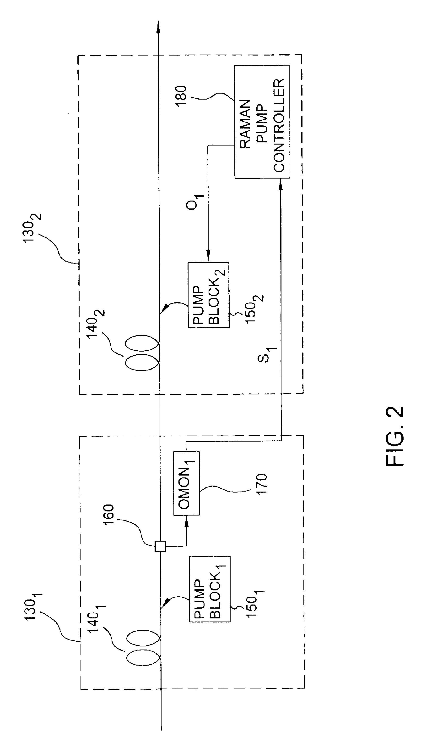
unable Raman pump block by the Raman pump controller;

[0018]FIG. 5 depicts an alternate embodiment of the present invention; and

[0019]FIG. 6 depicts a flow diagram of one embodiment of a method of the present invention.

[0020]To facilitate understanding, identical reference numerals have been used, where possible, to designate identical elements that are common to the figures.

DETAILED DESCRIPTION OF THE INVENTION

[0021]The invention will be described within the context of an all-Raman-pumped WDM system. However, it will be appreciated by those skilled in the art that the subject invention may be advantageously employed in any system utilizing at least one wavelength tunable Raman pump. The subject invention may also be advantageously employed in a hybrid systems comprising at least one wavelength tunable Raman pump as well as non-Raman optical pumps or sources.

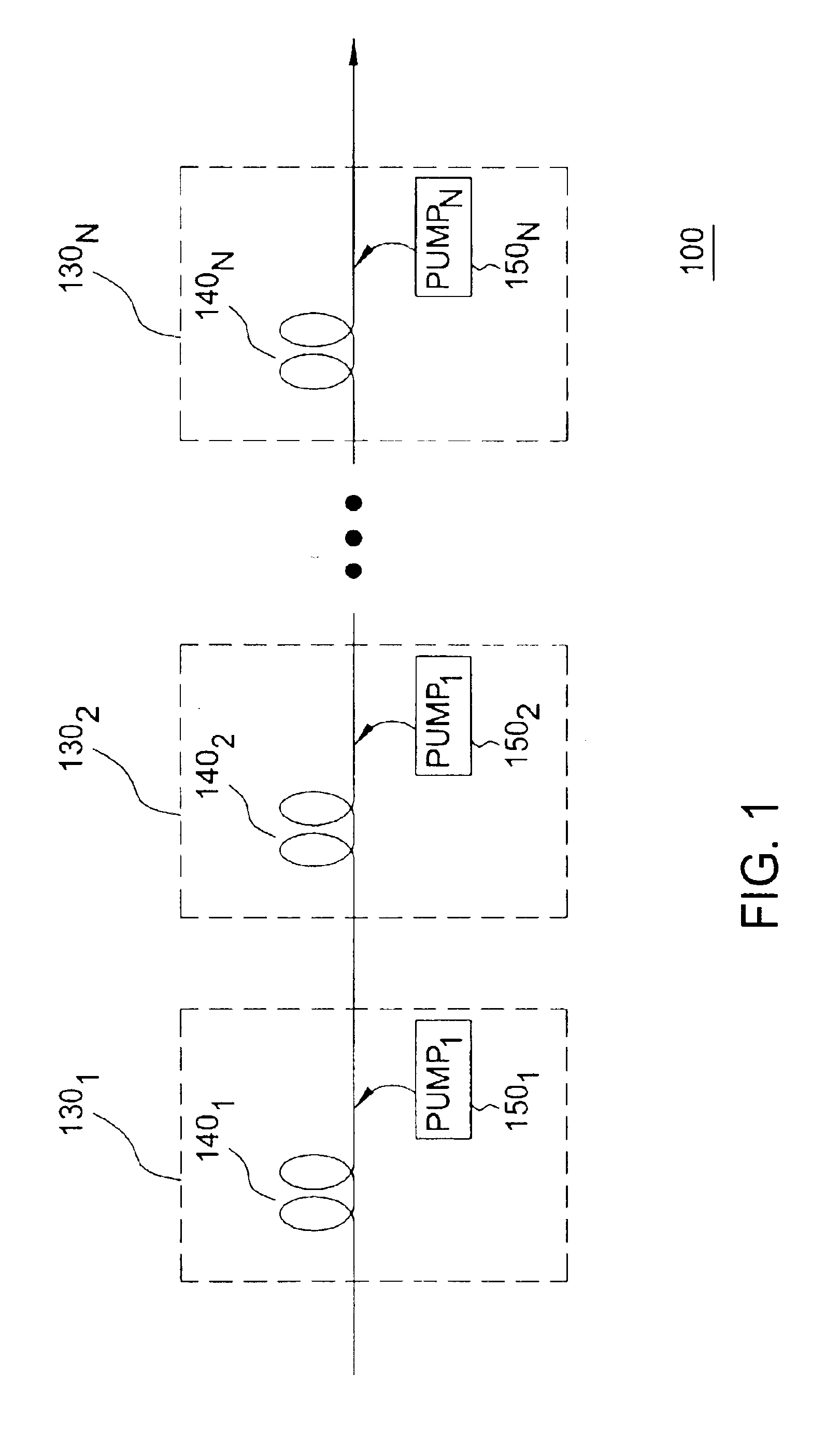
[0022]FIG. 1 depicts a high-level block diagram of a plurality of concatenated Raman amplification spans of an all-Raman-pumped...


PUM


Abstract

A method, apparatus and system for reducing gain ripple in a Raman-amplified WDM system includes determining a gain profile of an optical signal transported via a first Raman amplification span in a Raman-amplified WDM system, comparing the determined gain profile to a gain profile of an optical signal transported via a second Raman amplification span, determining, from the comparison, an amount of wavelength adjustment required for a plurality of Raman pumps comprising at least one Raman pump block of the second Raman amplification span to alter the gain profile of an optical signal transported via the second Raman amplification span, such that a cumulative gain profile of an optical signal transported via the first and the second Raman amplification spans approaches a desired gain profile, and generating a control signal suitable for adjusting the wavelengths of the plurality of Raman pumps of the at least one Raman pump block an amount consistent with the determined amount.

Description

FIELD OF THE INVENTION[0002]This invention relates to the field of optical communications and, more specifically, to Raman-pumped WDM systems.BACKGROUND OF THE INVENTION[0003]The demand for communication systems with higher capacities has pushed the common design approaches of wavelength-division-multiplexed (WDM) systems to their limits. A typical configuration of a point-to-point WDM system includes a number of optical transmitters, an optical multiplexer, spans of transmission fiber, optical amplifiers (usually erbium-doped fiber amplifiers, EDFAs), dispersion compensating devices, an optical demultiplexer and a number of optical receivers. Unfortunately, the usable gain bandwidth for the optical amplifiers currently used, for example the EDFAs, is limited and not very broad, and the distortion of the signal does not allow for transmission over very long optical transmission links. This has led to the investigation of alternate methods for amplification with greater broadband cap...

Claims


Application Information

Patent Timeline
IPC IPC(8): H01S3/00H04B10/17
CPCH04B10/2916H04B2210/003
Inventor FISHMAN, DANIEL A.HUNSCHE, STEFANLIU, XIANGMOVASSAGHI, MAHANXU, CHUNHUI
Owner WSOU INVESTMENTS LLC
Learn More