Method of producing an LED rope light

a technology of led rope light and led light, which is applied in the manufacture of contact members, semiconductor devices for light sources, light and heating apparatus, etc., can solve the problems of reducing the overall structural strength of the core tube, affecting the assembling process, and damaged the bulb in the core tube, so as to reduce the overall structural strength and reduce the cost

Inactive Publication Date: 2005-03-01
LIU LI WEN +1
View PDF3 Cites 18 Cited by
  • Summary
  • Abstract
  • Description
  • Claims
  • Application Information

AI Technical Summary

Benefits of technology

A primary object of the present invention is to provide a method that enables production of an energy saving, safe, and environment friendly LED rope light at reduced cost and shortened assembling time.
To achieve the above and other objects, the method of the present invention for producing an LED rope light includes the steps of preparing a plurality of light seats defining a recess therein and a plurality of metal wires having two conductive plates connected to two ends thereof; positioning two conductive plates from two d

Problems solved by technology

The existence of the longitudinal opening largely reduces an overall structural strength of the core tube.
When the rope light is used on a stage or at places close to steps and tends to be twisted, deformed, trodden or impacted, the core tube with reduced structural strength is not strong enough to bear such external forces, resulting in damaged bulbs in the core tube.
Moreover, it is difficult and requires increased material and labor costs to mount the insulated sleeves around the lead wires of two adjacent b

Method used


Image

  • Method of producing an LED rope light
  • Method of producing an LED rope light
  • Method of producing an LED rope light

Examples


Embodiment Construction

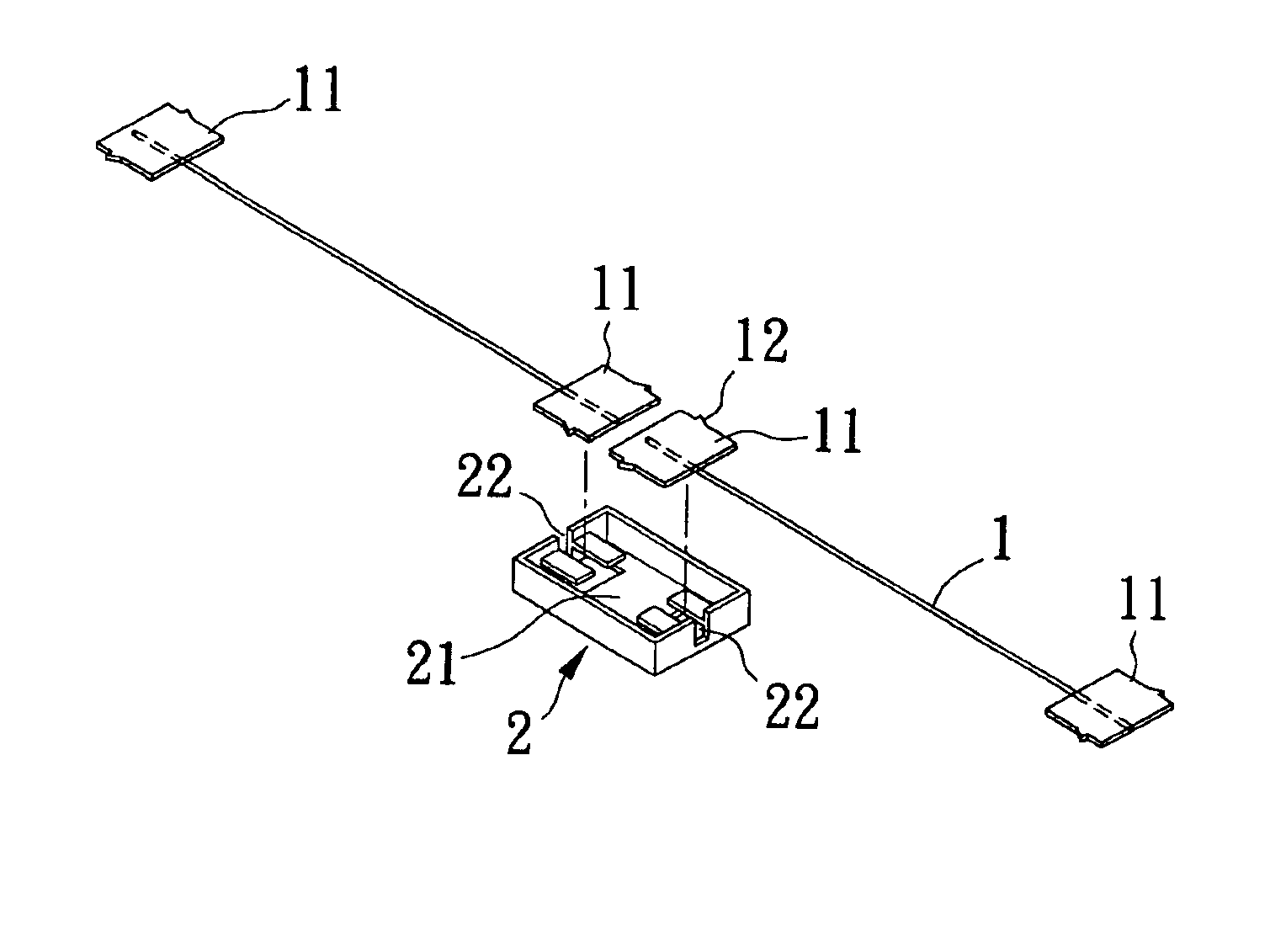
Please refer to FIGS. 1 to 7, in which different steps included in the method of the present invention for producing an LED light rope are illustrated.

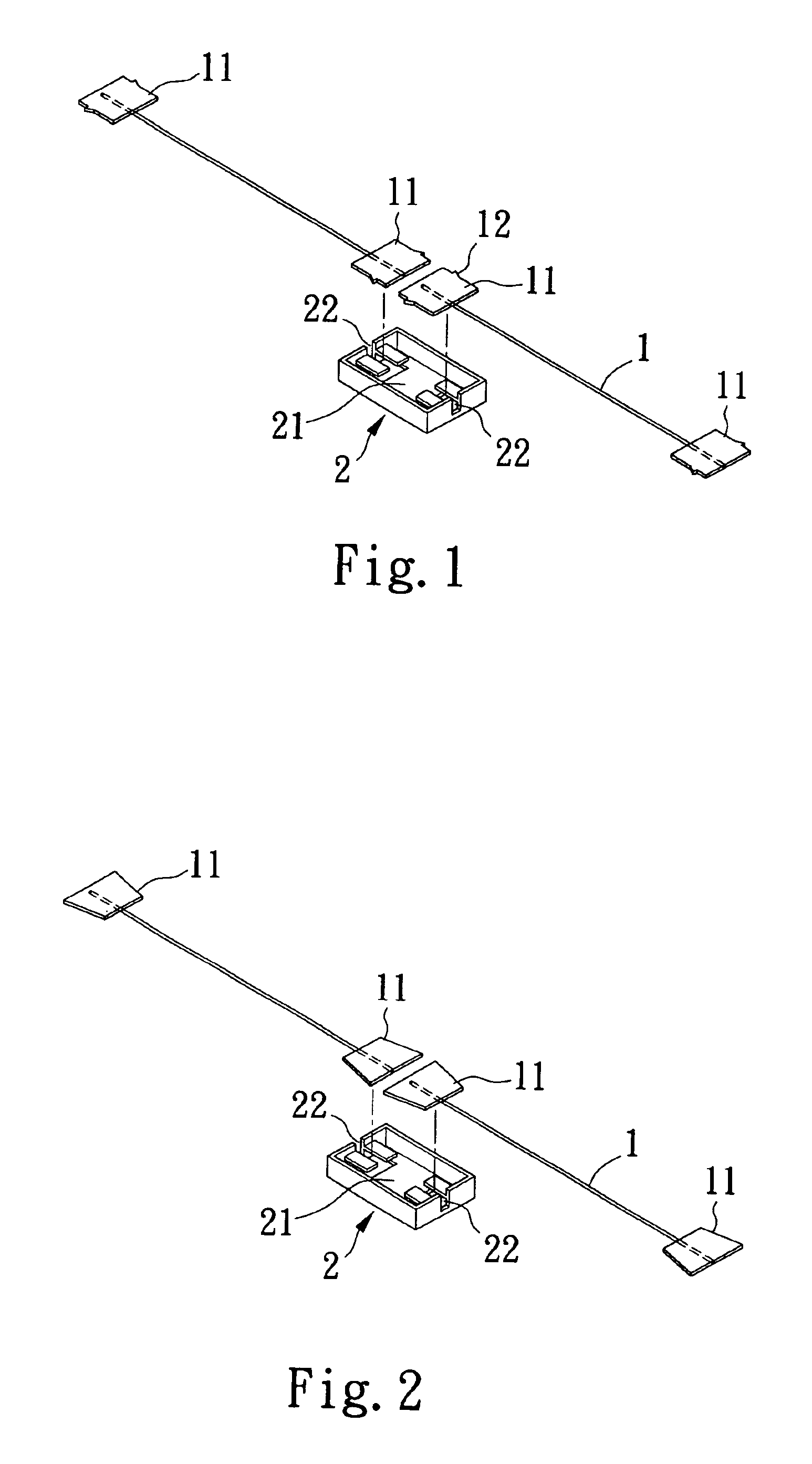
In the first step of the method of the present invention as shown in FIG. 1, a plurality of metal wires 1 having two rectangular conductive plates 11 connected to two ends thereof are prepared. Each of the conductive plates 11 is provided at two lateral sides with two oppositely projected teeth 12. There is also prepared a plurality of open-topped light seats 2, each of which defines a recess 21 therein. Each of the light seats 2 is provided at two transverse ends with two opposite and symmetrical notches 22. It is to be noted that the conductive plate 1 is not restricted to a rectangular plate but may be a trapezoidal plate having a shorter inner transverse end and a longer outer transverse end, as shown in FIG. 2.

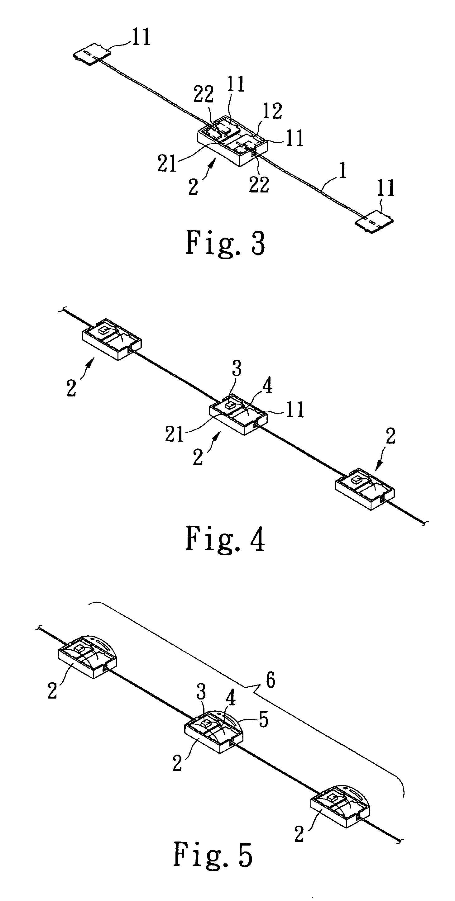
In the second step of the method of the present invention as shown in FIG. 3, the metal wires 1 are assembled to the ligh...


PUM

PropertyMeasurementUnit
Polarityaaaaaaaaaa
Electrical conductoraaaaaaaaaa
Transparencyaaaaaaaaaa

Abstract

A method of producing a light-emitting-diode (LED) rope light includes the steps of preparing a plurality of light seats defining a recess therein and a plurality of metal wires having two conductive plates connected to two ends thereof; positioning two conductive plates from two different metal wires in each light seat; forming the light seats into light-emitting diodes; serially connecting the light seats to provide an LED light string; positioning the LED light string into a hollow power cord holder with two electrodes of the LED light string connected to two power cords embedded in the power cord holder; and quickly enclosing said power cord holder with a transparent outer tube by way of injection molding to form an LED rope light.

Description

FIELD OF THE INVENTIONThe present invention relates to a method of quickly producing a light-emitting-diode (LED) rope light, and more particularly to a method of producing an LED rope light at largely reduced manufacturing cost and shortened time.BACKGROUND OF THE INVENTIONA conventional rope light includes a plurality of bulbs as its light sources. These bulbs are serially connected to one another to form one or two bulb strings, which are then set in a long core tube. The core tube is cut at an outer surface to provide a longitudinal opening, via which the bulb string or strings are positioned into the core tube. Two power cords having different polarities are embedded in two opposite sides of a wall of the core tube. The two embedded power cords are cut at staggered positions to expose bare wires, to which lead wires of the first and the last bulb in the bulb strings are separately electrically connected to emit light. The core tube with bulbs is then drawn into a transparent ou...

Claims


Application Information

Patent Timeline
IPC IPC(8): H05K13/00H05K3/30F21S4/00
CPCF21S4/007F21Y2101/02Y10T29/49208Y10T29/49117Y10T29/49169Y10T29/49139Y10T29/49204Y10T29/49147Y10T29/49162F21S4/26F21Y2115/10
Inventor LIU, LI-WENLIU, WEI-JEN
Owner LIU LI WEN
Why Eureka
Try Eureka