Transition molding

a technology of transition molding and molding parts, applied in the direction of treads, structural elements, building components, etc., can solve the problems of difficulty in covering the gap that may be formed, the use of flooring materials that are dissimilar in shape or texture, and the placement of conventional edge moldings

Inactive Publication Date: 2005-03-01
PERGO
View PDF48 Cites 153 Cited by
  • Summary
  • Abstract
  • Description
  • Claims
  • Application Information

AI Technical Summary

Benefits of technology

An adhesive, such as a glue, a microballoon adhesive, contact adhesive, or chemically activated adhesive including a water-activated adhesive, may be positioned on the tab, the foot, and the arms. Of course, such an adh

Problems solved by technology

A problem is encountered, however, flooring materials that are dissimilar in shape or texture are used.
For example, when a hard floor is placed adjacent a carpet, problems are encountere

Method used


Image

  • Transition molding
  • Transition molding
  • Transition molding

Examples


Embodiment Construction

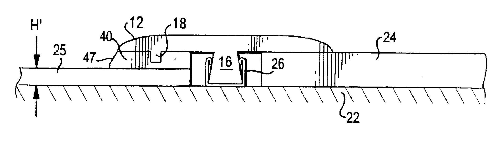
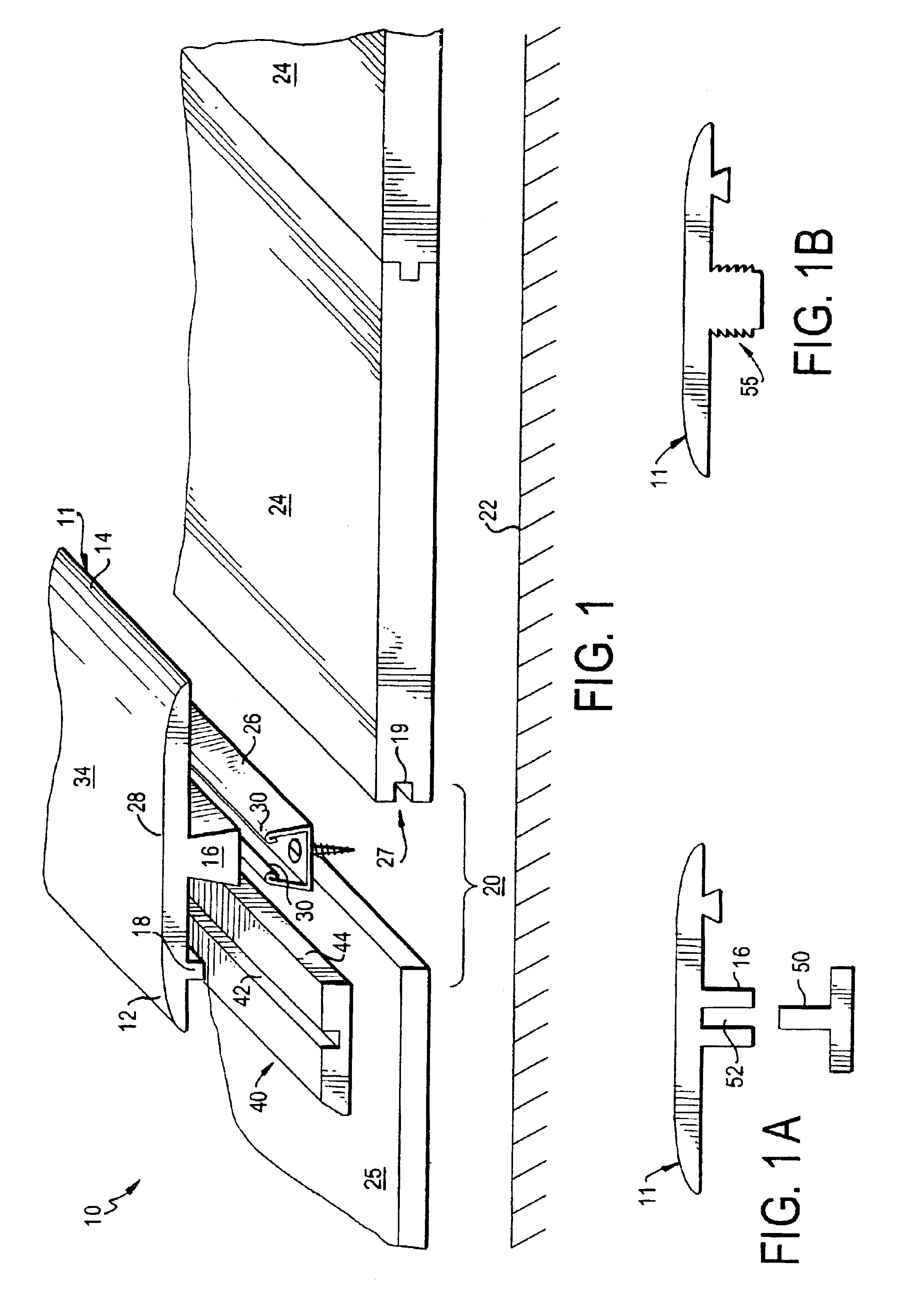
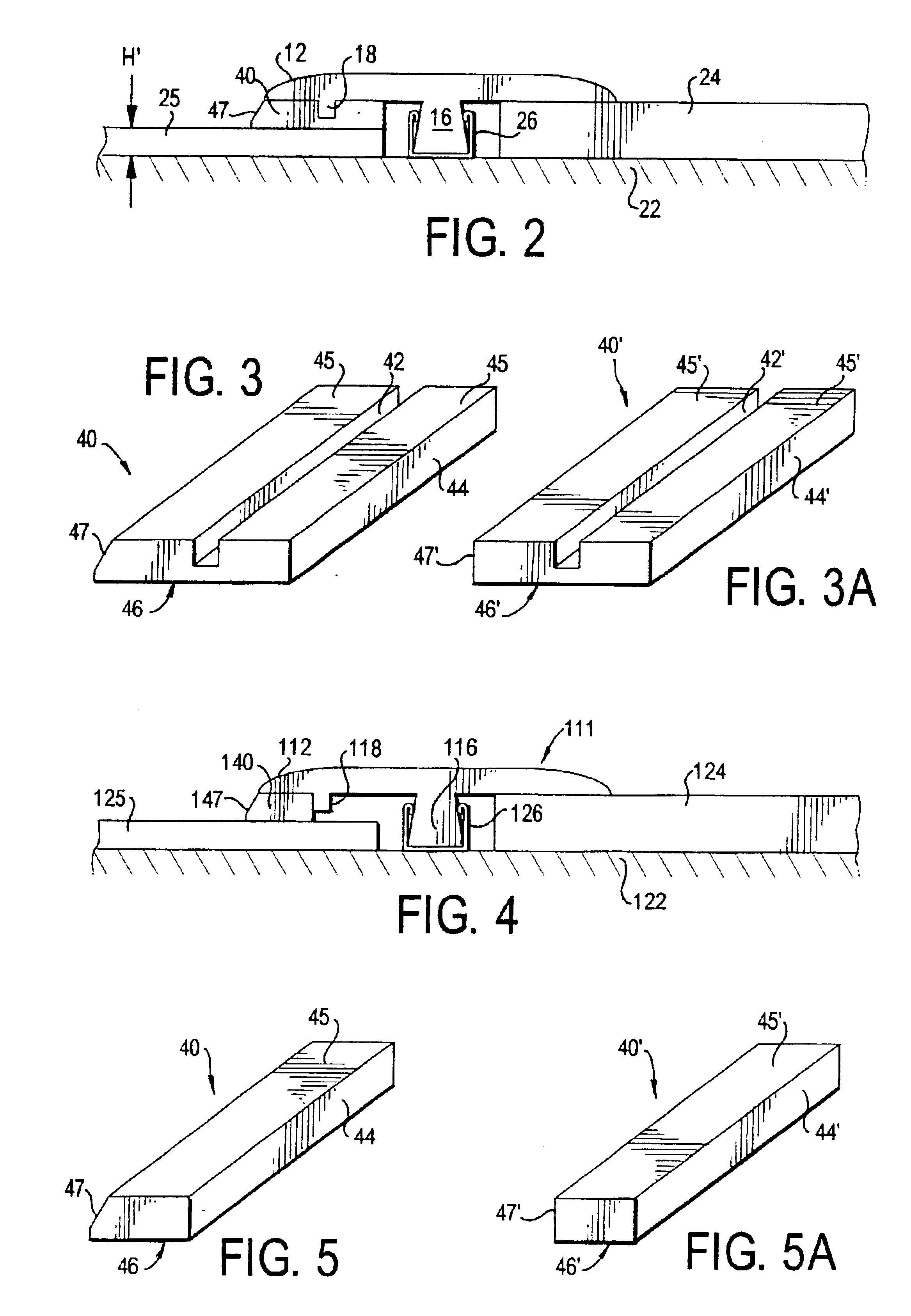
FIG. 1 shows an exploded view of the various parts of the inventive joint cover assembly 10. The assembly 10 includes a T-shaped molding 11, having an foot 16 formed so that it can fit in a gap 20 between adjacent floor elements 24, 25. FIG. 1 demonstrates a typical use, in which the gap 20 is formed adjacent an edge 27 of a floor element 24. Although FIG. 1, depicts all of the floor elements 24 to be conventional tongue-and-groove type floor panels (having a groove 27 positioned adjacent to the gap 20), this is merely one of any number of embodiments. For example, floor elements 24, 25 need not be the same type of floor element. Specifically, the floor elements 24 can be any type of flooring designed to used as a floor or placed over a subfloor 22, e.g., tile, linoleum, laminate flooring, concrete slab, parquet, vinyl, turf, composite or hardwood. As is known, laminate floors are not attached to the subfloor 22, but are considered “floating floors”.

The molding 11 is provided with a...


PUM


Abstract

The invention is a joint cover assembly for covering a gap adjacent an edge of a panel that covers a sub-surface, and a method of covering such a gap. The assembly includes a molding having a foot, a first arm, and a second arm. The foot is positioned along a longitudinal axis, and the first arm extends generally perpendicularly from the foot. The second arm extends generally perpendicularly from the foot. A tab depends generally perpendicularly from the first panel engaging surface. At least one of the tab and the foot engage the edge in order to tightly fit within the gap. The method includes the steps of placing the foot in the gap, pressing the respective panel engaging surfaces into contact with respective panels, and configuring at least one of the tab and the foot to cooperate to retain the molding in the gap when the assembly is in an installed condition.

Description

BACKGROUND1. Field of the InventionThe invention is a joint cover assembly that includes a molding, similar to a T-Molding, for covering a gap that may be formed adjacent a panel in a generally planar surface, such as between two adjacent flooring materials, a floor and a wall, or a riser and a runner in a step (or a series of steps).2. Background of the InventionWood or laminate flooring has become increasingly popular. As such, many different types of this flooring have been developed. Generally, this type of flooring is assembled by providing a plurality of similar panels. The differing types of panels that have developed, of course, may have differing depths and thicknesses. Thus, when panels having different thicknesses are placed adjacent to each other, transition moldings are often used to create a smooth joint.Additionally, one may desire to install floor panels adjacent to an area with different types of material. For example, one may desire to have one type of flooring in ...

Claims


Application Information

Patent Timeline
IPC IPC(8): E04F19/02E04F19/06E04F15/02E04F11/16
CPCE04F15/02005E04F19/06E04F11/166E04F19/062E04F19/065E04F19/066E04F15/02016E04F19/061E04F11/163E04F19/02E04F19/063
Inventor STANCHFIELD, OLIVER
Owner PERGO
Why Eureka
Try Eureka