
Liquid propellant tracing impingement injector

a technology of injector and propellant, which is applied in the direction of rocket engine plants, jet propulsion plants, machines/engines, etc., can solve the problems of increasing the complexity of the injector, affecting the performance of the injector, and requiring a long time to fabricate traditional injectors, etc., and achieves the effect of low cos

Inactive Publication Date: 2005-03-01
NASA
View PDF16 Cites 19 Cited by
  • Summary
  • Abstract
  • Description
  • Claims
  • Application Information

AI Technical Summary

Benefits of technology

Consequently, it is a primary object of the present invention to provide a low cost injector to be used in rocket engines or other combustion chambers.
Accordingly, a tracing impingement injector has a plurality of fuel ports separated from a plurality of oxidizer ports. The oxidizer and fuel ports direct fuel and oxidizer into the combustion chamber with a radial and tangential component such that the two fluids impinge a predetermined spaced apart distance from the chamber wall. It is further preferred that the fuel be introduced closer to the chamber walls so that the fuel provides a fuel rich zone near the wall to assist in cooling to the wall and to eliminate the wall oxidation during operation.

Problems solved by technology

These cooling concerns are believed to create a loss in performance.
Additionally, traditional injectors often require a long time to fabricate and are usually costly to produce.
The impeller design is believed to add to the complexity of the injector and possibly provide a point of failure and increased costs.
These thermal stresses are believed to be high enough to drastically reduce the life of the components.

Method used


Image

  • Liquid propellant tracing impingement injector
  • Liquid propellant tracing impingement injector
  • Liquid propellant tracing impingement injector

Examples


Embodiment Construction

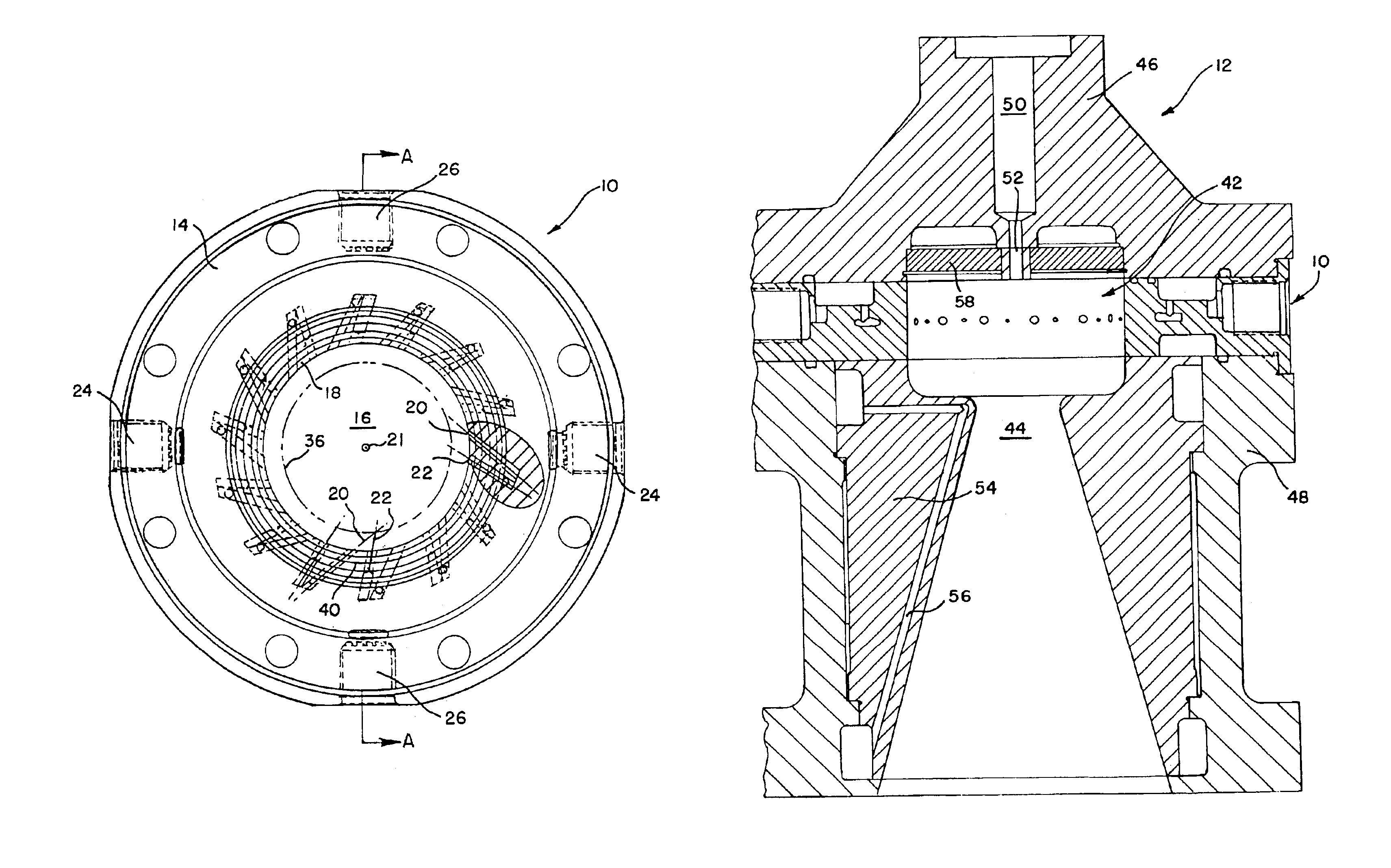
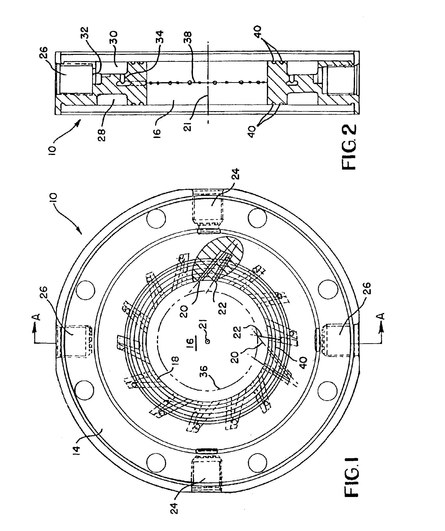
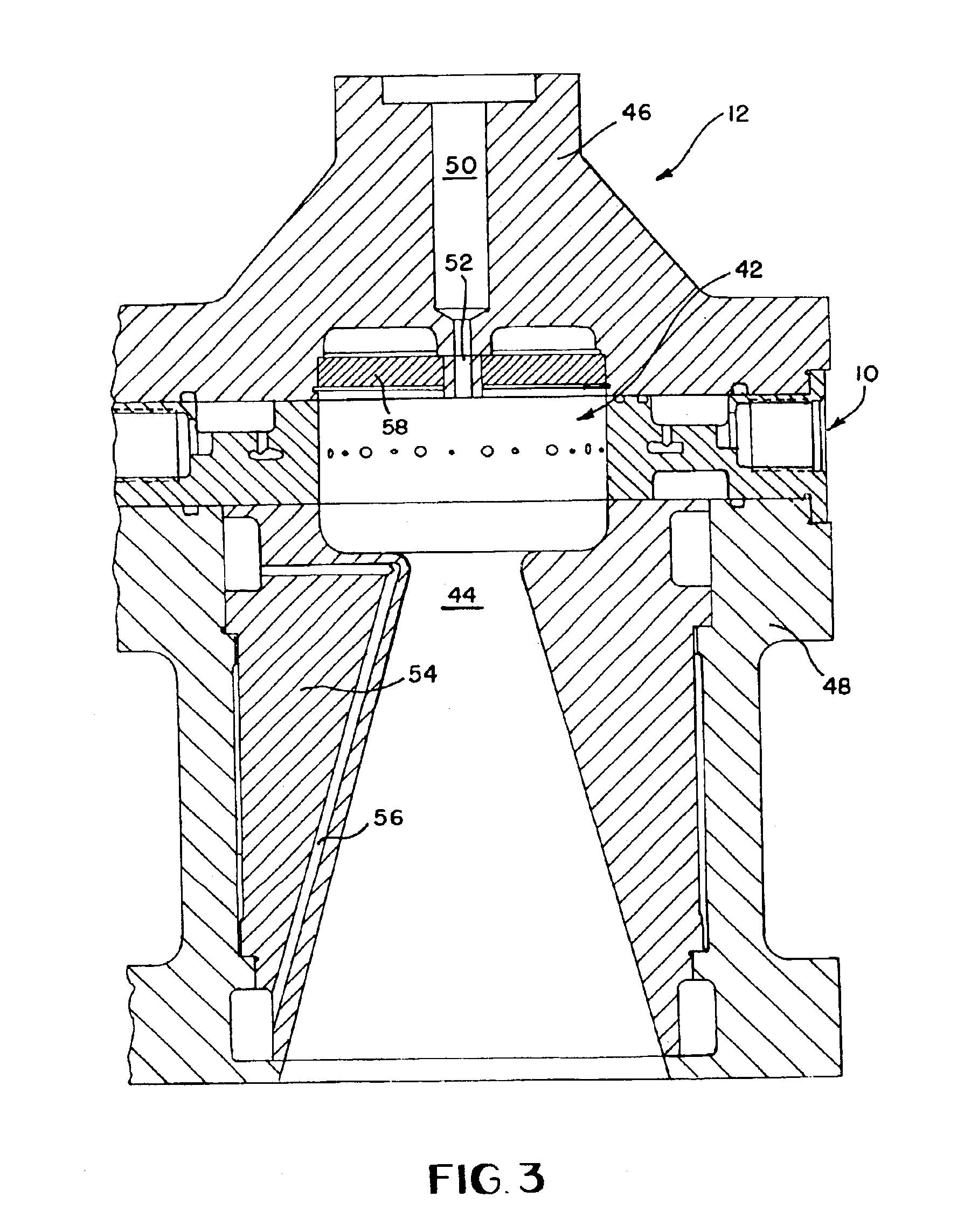
Referring to FIGS. 1 and 2, a liquid propellant injector 10 is disclosed for use in a rocket thruster 12 as shown in FIG. 3. Referring back to FIGS. 1 and 2, the injector 10 is comprised of a housing 14 containing a combustion chamber 16 therein. The combustion chamber is defined by chamber walls 18 which surround the chamber 16. The chamber walls 18 have ports 20,22 which will be explained in more detail below which provide fuel and oxidizer to the combustion chamber 16. Fuel and oxidizer are often referred to as propellants herein. By fabricating the housing 14 with a three-dimensional computer aided design model, a laser engineered net shaping (LENS) machine was able to shape the combustion chamber 16 in the housing 14 and provide ports 20,22 as illustrated. Ports 20 are preferably utilized to provide oxidizer into the combustion chamber. Ports 22 are preferably utilized to provide fuel into the combustion chamber 16.

Inlet ports 24 receive oxidizers such as liquid oxygen from a s...


PUM


Abstract

An injector for use with the rocket thruster has a plurality of fuel ports separated from a plurality of oxidizer ports. The oxidizer and fuel ports are paired together directing their respective fluids along a path with radial and tangential components so that the two fluids impinge at a predetermined spaced apart distance from the chamber wall of the combustion chamber at an impingement track. By providing the fuel at a steeper angle relative to the chamber walls than the oxidizer, the fuel can be utilized to provide a fuel rich zone near the chamber walls to assist in cooling the chamber walls during operation.

Description

BACKGROUND OF THE INVENTION1. Field of the InventionThis invention relates to a liquid propellant injector for use with a rocket thruster, more particularly to an improved injector defining combustion chamber therein.2. Prior ArtVarious injectors have been utilized with rocket propulsion systems in the past. U.S. Pat. No. 5,765,361 shows an injector which provides the oxidizer as well as the fuel axially in the direction of a nozzle. The igniter engine shown in FIG. 1A initially provides oxidizer to start the combustion process. Axially directed propellants typically take a relatively long combustion chamber to ensure that propellants mix and completely combust prior to exiting the nozzle.U.S. Pat. No. 4,586,226 operates somewhat similarly to the '361 patent. Fuel is provided axially in the direction of the nozzle in the illustrated injector from a face plate at the chamber head end. In this design, the oxidizer is directed at an angle to intersect the flow path of the fuel and then...

Claims


Application Information

Patent Timeline
IPC IPC(8): F02K9/97F02K9/00F02K9/62
CPCF02K9/972F02K9/62
Inventor XENOFOS, GEORGE D.MYERS, W. NEILLTRINH, HUUMICHAELS, R. SCOTT
Owner NASA
Learn More