
Electronic throttle control hysteresis mechanism

Inactive Publication Date: 2005-03-01
DURA GLOBAL TECH
View PDF22 Cites 34 Cited by
  • Summary
  • Abstract
  • Description
  • Claims
  • Application Information

AI Technical Summary

Benefits of technology

The present invention provides a control pedal assembly which overcomes at least some of the above-noted problems of the related art. According to the present invention, a control pedal assembly comprises, in combination, a support structure having a guide surface and a pedal arm carrying a pedal at a lower end of the pedal arm. The pedal arm is pivotable relative to the support structure about a pivot axis between a released position and an applied position. A hysteresis device is secured to an upper end of the pedal arm and engages the guide surface so that the hysteresis device moves along the guide surface as the pivot arm pivots between the released position and the applied position. A distance between the guide surface and the pivot axis varies so that the hysteresis device applies an increasing normal force to the guide surface to create an increasing friction force that opposes motion of the hysteresis device as the pedal arm pivots from the released position to the applied position.
According to another aspect of the present invention, an electronic control pedal assembly comprises, in combination, a support structure having a first guide surface and a second guide surface spaced apart from and facing the first guide surface and a pedal arm carrying a pedal at a lower end of the pedal arm. The pedal arm is pivotable relative to the support structure about a pivot axis between a released position and an applied position. A sensor is operably connected to the pedal arm and provides electronic signals responsive to pivotable movement of the pedal arm about the pivot axis. A hysteresis device is secured to the pedal arm and is engagable with the first and second guide surfaces so that the hysteresis device slides along the first and second guide surfaces as the pivot arm pivots between the released position and the applied position. A distance between the guide surfaces decreases in a direction of travel of the hysteresis device as the pedal arm pivots from the release position to the applied position so that an increasing interference between the support structure and the hys

Problems solved by technology

The pressure required to advance the control pedal is easily provided when accelerating but would become uncomfortable over time to maintain a relatively constant speed.
While these proposed control pedals may adequately provide the “feel” of a control pedal with a mechanical linkage, they are relatively complex and expensive to produce.
Additionally, the proposed control pedals require a relatively large amount of space.

Method used


Image

  • Electronic throttle control hysteresis mechanism
  • Electronic throttle control hysteresis mechanism
  • Electronic throttle control hysteresis mechanism

Examples


Embodiment Construction

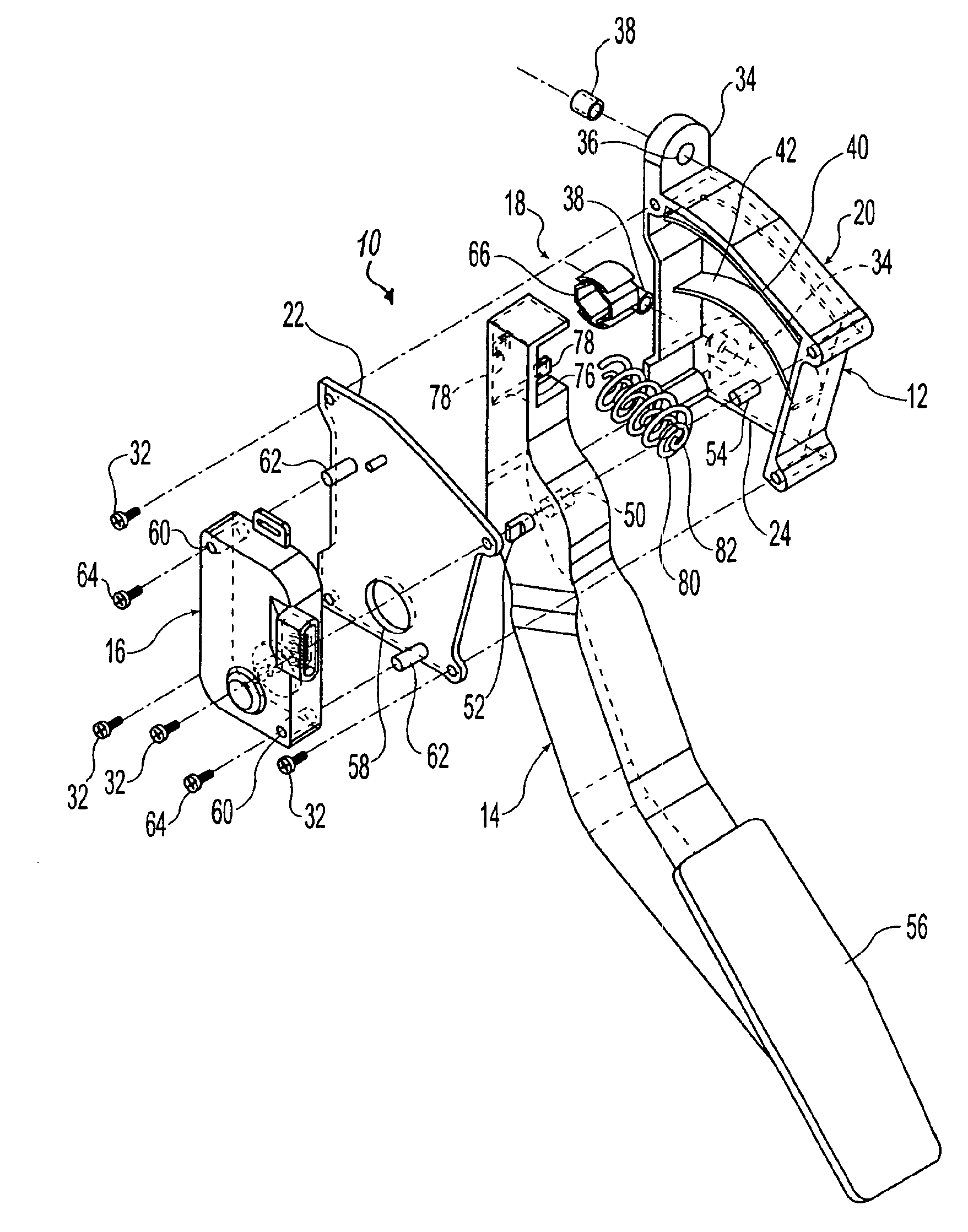
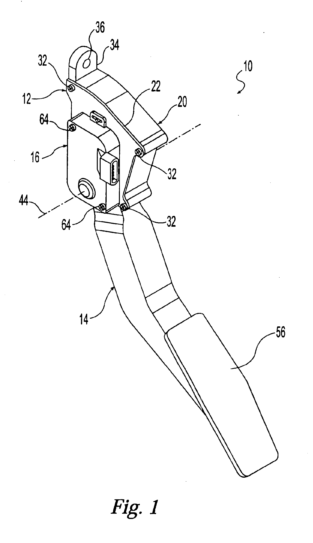
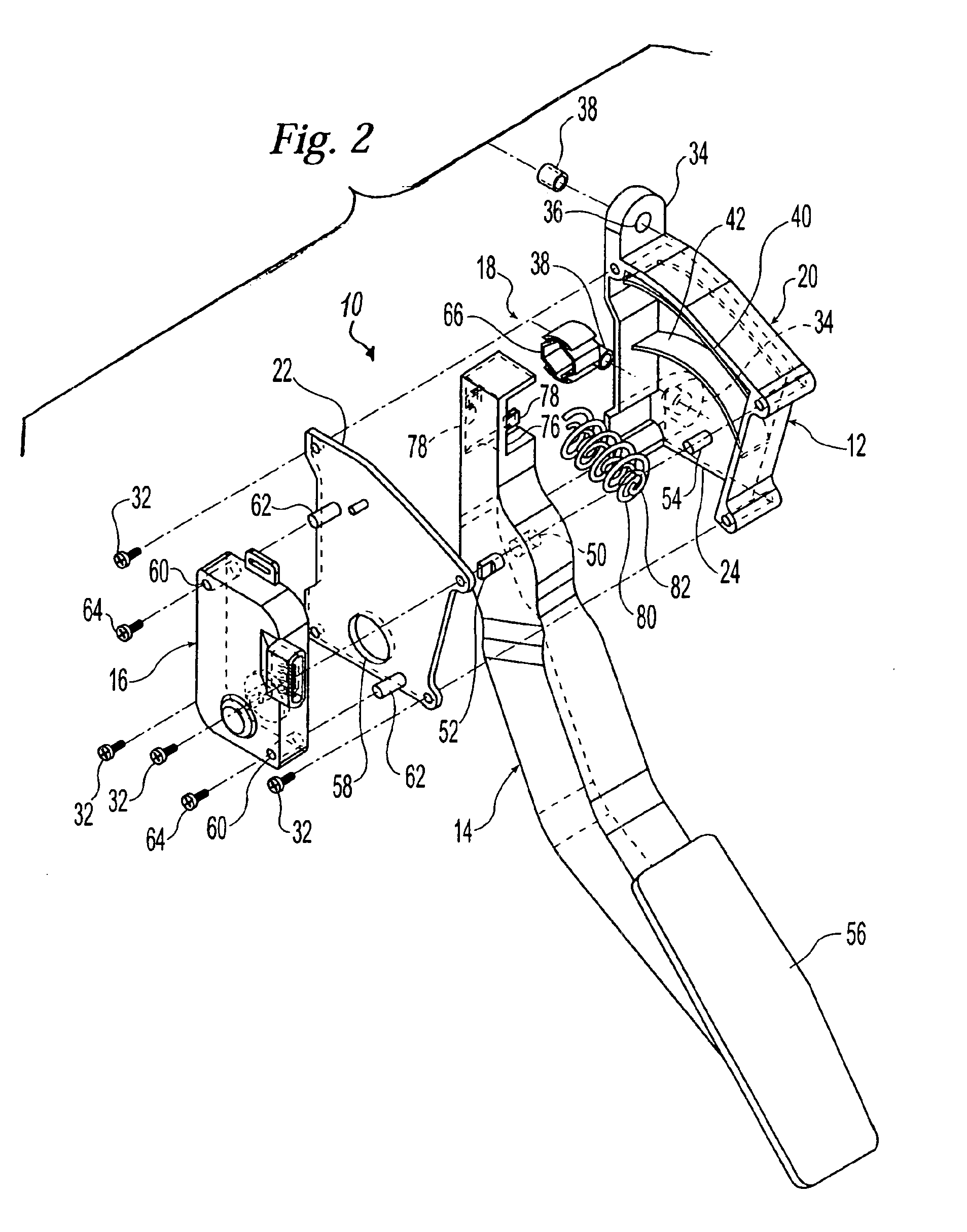
It will be apparent to those skilled in the art, that is, to those who have knowledge or experience in this area of technology, that many uses and design variations are possible for the improved control pedal assemblies disclosed herein. The following detailed discussion of various alternative and preferred embodiments will illustrate the general principles of the invention with reference to an electronic accelerator pedal for use with an automobile. Other embodiments suitable for other applications, such as brake or clutch pedals and / or other types of motor vehicles, will be apparent to those skilled in the art given the benefit of this disclosure. The present invention can be utilized with any vehicle having a foot operated control pedal including trucks, buses, vans, recreational vehicles, earth moving equipment and the like, off road vehicles such as dune buggies and the like, air borne vehicles, and water borne vehicles.

Referring now to the drawings, FIGS. 1 to 3 show a control...


PUM


Abstract

A control pedal assembly includes a support structure having a guide surface and a pedal arm carrying a pedal at a lower end of the pedal arm. The pedal arm is pivotable relative to the support structure about a pivot axis between a released position and an applied position. A hysteresis device is secured to an upper end of the pedal arm and engages the guide surface so that the hysteresis device slides along the guide surface as the pivot arm pivots between the released position and the applied position. A distance between the guide surface and the pivot axis varies so that the hysteresis device applies an increasing normal force to the guide surface to create an increasing friction force that opposes sliding motion of the hysteresis device as the pedal arm pivots from the released position to the applied position.

Description

CROSS-REFERENCE TO RELATED APPLICATIONSNot ApplicableSTATEMENT REGARDING FEDERALLY SPONSORED RESEARCHNot ApplicableREFERENCE TO MICROFICHE APPENDIXNot ApplicableFIELD OF THE INVENTIONThe present invention generally relates to a control pedal assembly for a motor vehicle and, more particularly, to a control pedal assembly for a motor vehicle which is electronically coupled and has a mechanical hysteresis device to simulate the feel of a control pedal assembly which is mechanically coupled.BACKGROUND OF THE INVENTIONControl pedals are typically provided in a motor vehicle, such as an automobile, which are foot operated by the driver. Separate control pedals are provided for operating brakes and an engine throttle. When the motor vehicle has a manual transmission, a third control pedal is provided for operating a transmission clutch. The control pedals are typically connected to control devices by push-pull cables, rods, or other mechanical transmission devices which convert the limite...

Claims


Application Information

Patent Timeline
IPC IPC(8): G05G1/38
CPCG05G1/30Y10T74/20888Y10T74/2054Y10T74/20528
Inventor DEFOREST, JASON DALE
Owner DURA GLOBAL TECH
Learn More