Threading apparatus for sewing machine

a technology for sewing machines and threading devices, applied in sewing apparatuses, needle bars, textiles and paper, etc., can solve problems such as problems, and achieve the effect of smooth movemen

Inactive Publication Date: 2005-03-01
BROTHER KOGYO KK
View PDF9 Cites 4 Cited by
  • Summary
  • Abstract
  • Description
  • Claims
  • Application Information

AI Technical Summary

Benefits of technology

Therefore, an object of the present invention is to provide a threading apparatus in which an amount of operation required for the threading operation is small.
In another preferred form, the moving actuating member or the transmitting actuating member comprises a pulley engaging the middle portion of the string-shaped member. The operating member can smoothly be moved by use of the pulley.

Problems solved by technology

This poses a problem.

Method used


Image

  • Threading apparatus for sewing machine
  • Threading apparatus for sewing machine
  • Threading apparatus for sewing machine

Examples


Embodiment Construction

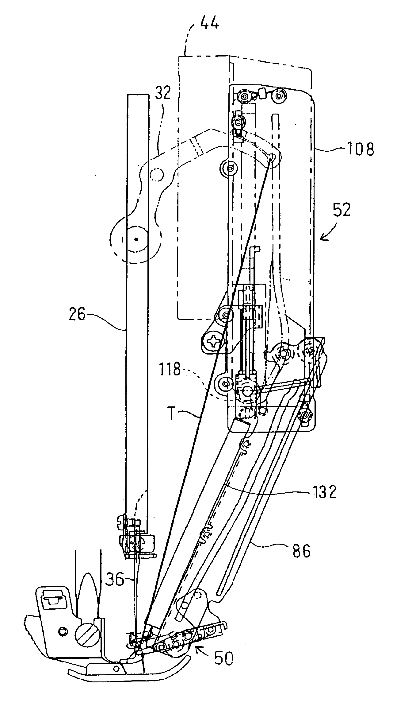
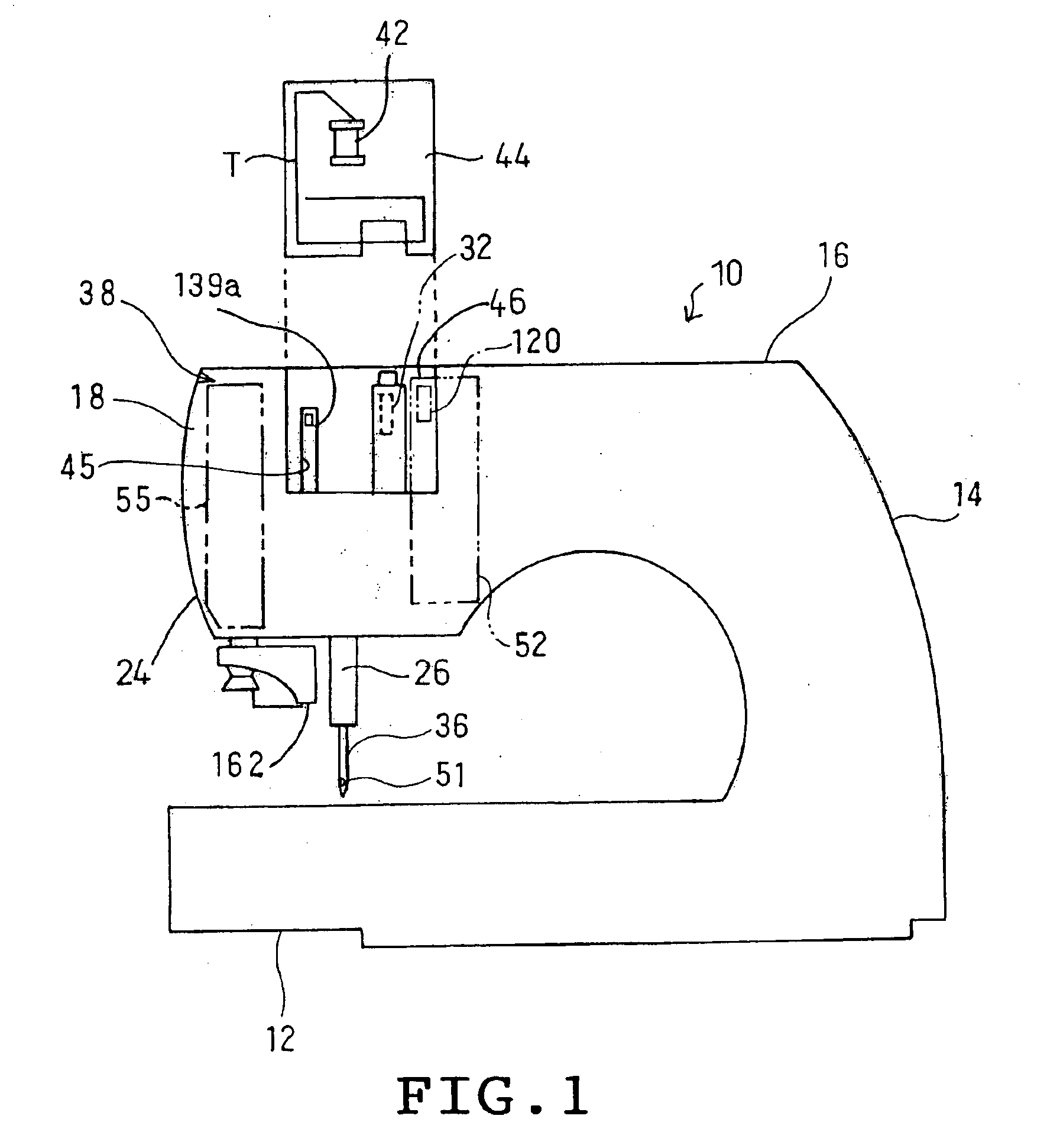
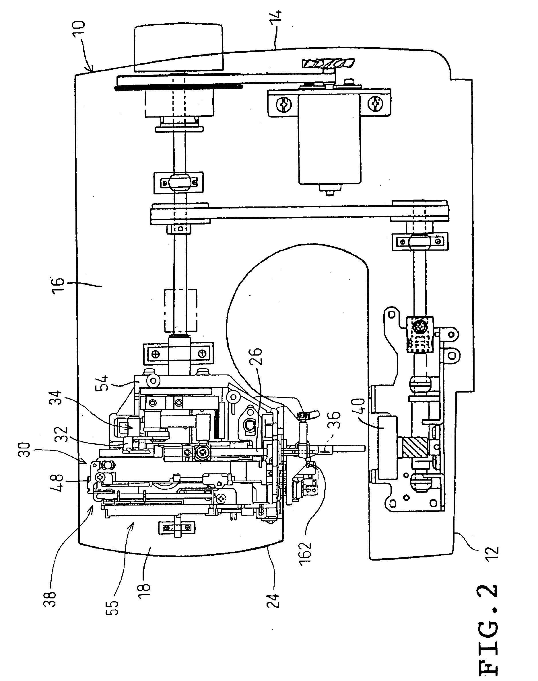
One embodiment of the invention will be described with reference to the accompanying drawings. Referring to FIGS. 1 and 2, a sewing machine 10 to which the threading apparatus of the invention is applied is schematically shown. The sewing machine 10 comprises a sewing bed 12 having a horizontal plane, a pillar 14 standing from a right end of the bed 12 and a sewing arm 16 extending rightward from an upper end of the pillar 14 and a machine head 18 located at a left end of the arm 16. A needle bar 26 extends downward from the head 18. A sewing needle 36 is detachably attached to a lower end of the needle bar 26. The head 18 encloses a needle bar driving mechanism 28 for moving the needle bar 26 up and down, a needle bar swinging mechanism 30 for swinging the needle bar 26 horizontally, a needle thread take-up driving mechanism 34 interlocked with the movement of the needle bar driving mechanism 28 for moving the needle thread take-up 32 up and down, and a threading mechanism 38 for p...


PUM


Abstract

A threading apparatus for a sewing machine includes a moving mechanism for moving a threading member between a first position where the threading member is close to a needle eye and a second position where the threading member is away from the needle eye. The moving mechanism includes a moving actuating member, a transmitting actuating member, a transmitting string-shaped member, and a moving string-shaped member. The transmitting string-shaped member is moved in such a direction that the moving actuating member is moved from a non-operative position to an operative position when the operating member is operated so that the transmitting actuating member is moved. The moving actuating member is moved from the non-operative position to the operative position so that the moving string-shaped member is moved in such a direction as to draw the supporting member.

Description

BACKGROUND OF THE INVENTION1. Field of the InventionThis invention relates generally to sewing machines and more particularly to a threading apparatus for automatically passing sewing thread through a needle eye in the sewing machines.2. Description of the Related ArtJP-B-7-71596 discloses a threading apparatus for a sewing machine comprising a threading hook coming close to and going away from a needle eye, a holding member for holding a sewing thread, a threading bar for supporting the hook and the holding member, and a threading lever for moving the threading bar up and down, for example. The disclosed threading apparatus is disposed above a movement range of the needle so as to be prevented from collision with the needle.In the foregoing threading apparatus, the threading lever is pressed down so that the threading bar is moved downward together therewith. When the threading lever is moved downward to a lowermost position thereof, the threading hook is at the same level as the n...

Claims


Application Information

Patent Timeline
Patent Type & Authority Patents(United States)
IPC IPC(8): D05B53/00D05B87/00D05B87/02
CPCD05B87/02D05B53/00
Inventor FUKAO, HIROAKI
Owner BROTHER KOGYO KK
Why Eureka
Try Eureka