Method for extracting round area from fringe pattern

An image area and stripe image technology, applied in the field of stripe image extraction circular area, can solve the problem of taking time to extract circular image area and so on

Inactive Publication Date: 2004-01-21
FUJI PHOTO OPTICAL CO LTD
View PDF1 Cites 1 Cited by
  • Summary
  • Abstract
  • Description
  • Claims
  • Application Information

AI Technical Summary

Problems solved by technology

[0013] However, this conventional circular area extraction method has a problem in that it takes time to extract the circular image area because the template has to be gradually moved on the coordinate system over the entire image area with the captured fringe image

Method used


Image

  • Method for extracting round area from fringe pattern
  • Method for extracting round area from fringe pattern
  • Method for extracting round area from fringe pattern

Examples


no. 1 example

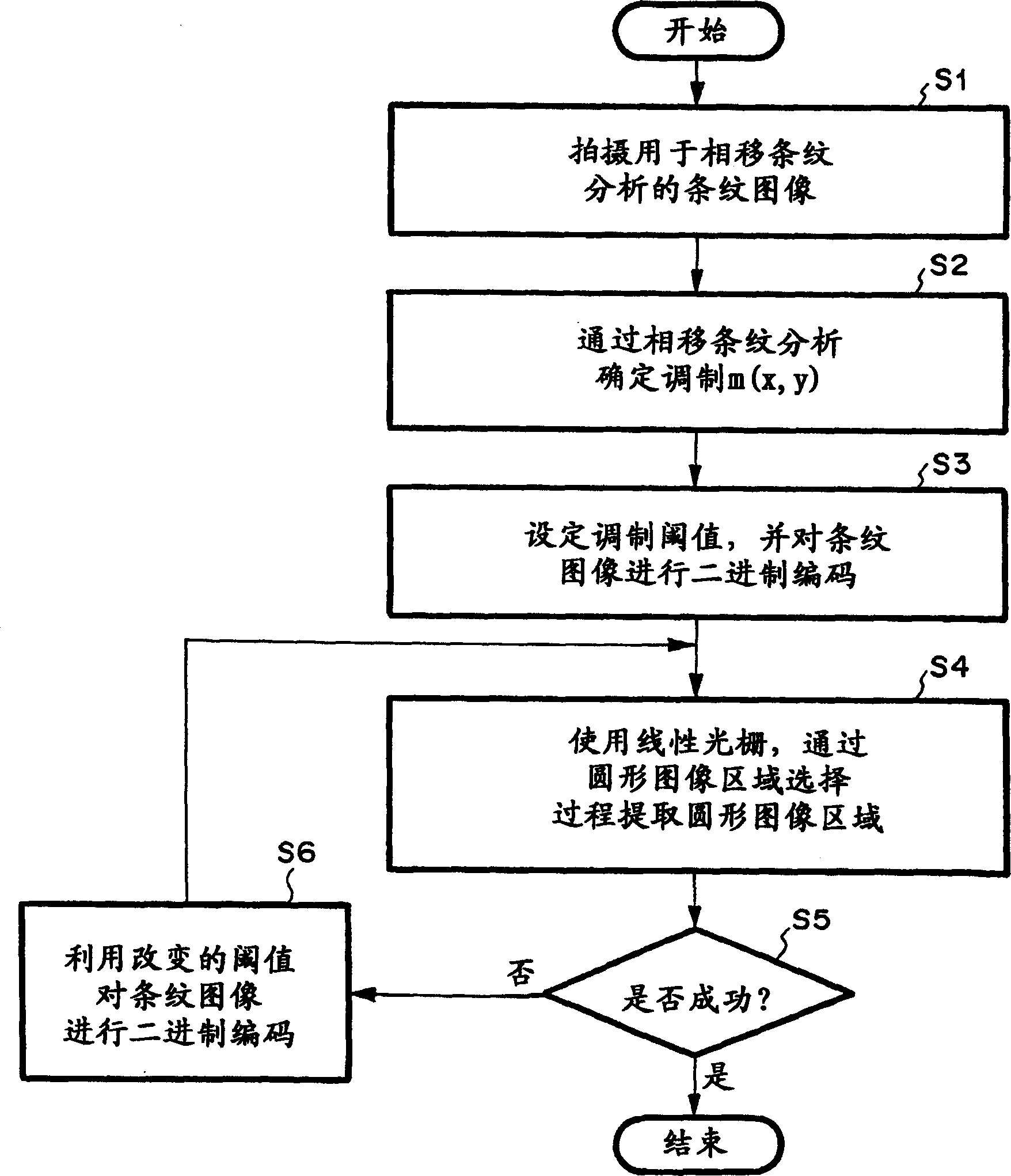
[0041] First, refer to figure 1 An outline of a method of extracting a circular region from a fringe image according to the first embodiment of the present invention will be described. figure 1 is a flow chart, representing a schematic process of the method according to the first embodiment of the present invention.

[0042] The method according to the first embodiment of the present invention uses a phase shift fringe analysis method. The phase shift fringe analysis method is also called the fringe scanning fringe analysis method, which changes the optical path length difference between the object light and the reference light by changing the gap between the reference plane and the sample in the interferometer device, and the interference fringe The change in (interference fringe shift) determines the phase distribution of the sample.

[0043] First, multiple fringe images for the phase-shift fringe analysis method for a sample (such as a sleeve) having a circular area to...

no. 2 example

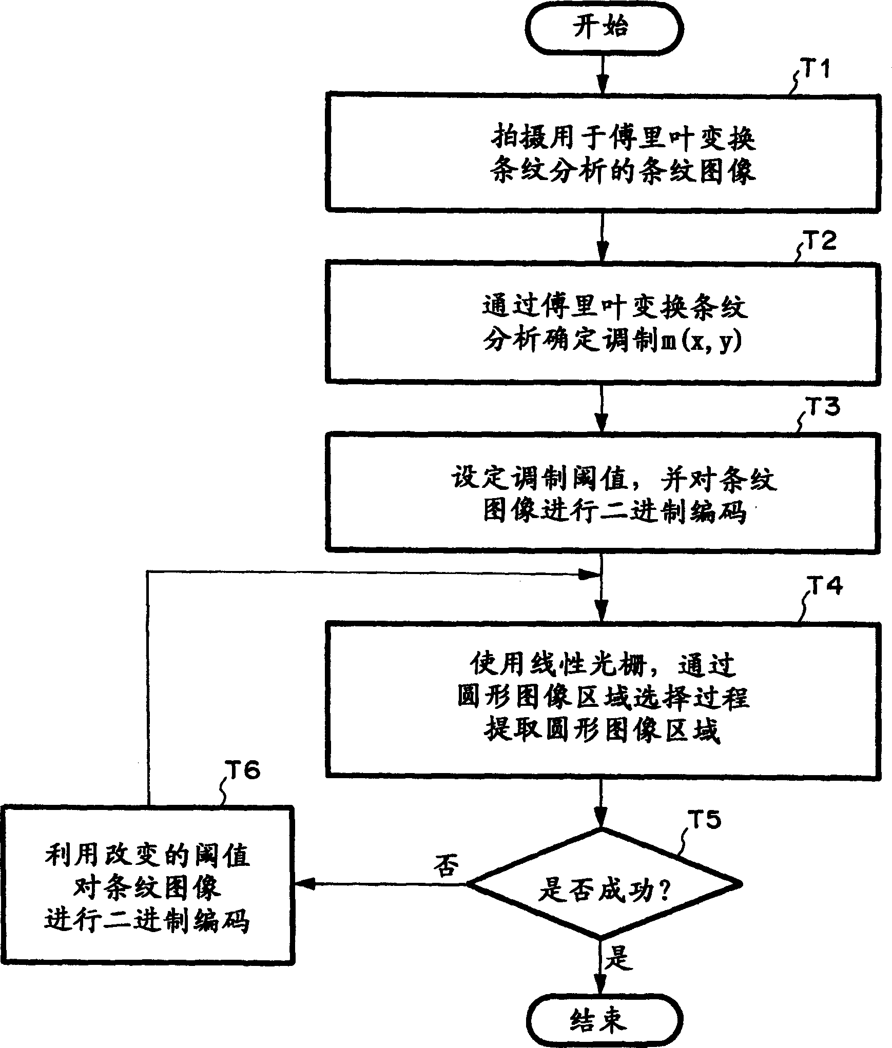
[0062] will now refer to image 3 An outline of a method of extracting a circular region from a fringe image according to the second embodiment of the present invention will be described. image 3 is a flow chart, representing a schematic process of the method according to the second embodiment of the present invention.

[0063] The method according to the second embodiment of the present invention uses a Fourier transform fringe analysis method. This Fourier transform fringe analysis method is a method of inclining the sample or reference surface to obtain a fringe image superimposed with a spatial frequency, and subjecting the obtained fringe image data to a series of Fourier transform operations to determine The phase distribution method of the sample.

[0064] First, for a sample (such as a casing) with a circular area to be analyzed in the observed area, a fringe image used in the above-mentioned Fourier transform analysis method, that is, a fringe image superimposed wi...


PUM


Abstract

A circular region extracting method captures onto a coordinate system a fringe image of a sample having a circular region to be analyzed within an area to be observed, binary-codes the fringe image of the area by a fringe analysis method on the coordinate system, places a plurality of linear gratings in parallel with each other with a predetermined interval on thus binary-coded coordinate system, and uses the linear gratings so as to extract a circular image region representing the region to be analyzed on the coordinate system.

Description

[0001] related application [0002] This application claims priority from Japanese Patent Application No. 2002-191404 filed on June 28, 2002, which is incorporated herein by reference. Background of the invention [0003] field of invention [0004] The invention relates to a method for extracting circular regions from fringe images. The method extracts (extracts) on the coordinate system of the fringe image with the captured (captured) fringe image carrying phase information (such as the surface shape and intrinsic refractive index of the sample with a circular area to be analyzed within the observed area). A circular image area representing the area being analyzed. [0005] Related technical description [0006] Recently, research and development on optical fibers used in optical communications has been active. A known example of such an optical fiber is, for example, a core comprising a core having an outer diameter of about 10 μm, and a cladding having an outer diam...

Claims


Application Information

Patent Timeline
Patent Type & Authority Applications(China)
IPC IPC(8): G01B11/24G06T5/00
CPCG06T2207/20012G06T2207/30108G06T2207/20056G06T7/0081G06T2207/20148G06T7/0004G06T2207/10056G06T7/11G06T7/136
Inventor 葛宗涛
Owner FUJI PHOTO OPTICAL CO LTD
Why Eureka
Try Eureka