Technique and platform for fabricating a variable-buoyancy structure

Inactive Publication Date: 2005-03-01
DEMPSTER HARRY EDWARD
View PDF37 Cites 28 Cited by
  • Summary
  • Abstract
  • Description
  • Claims
  • Application Information

AI Technical Summary

Benefits of technology

In more particularized aspects, the mold provides the variable-buoyancy structure with a laterally extending shoulder around the periphery of the variable-buoyancy structure. This often can help to prevent the structure from sinking too deeply into the material at the bottom o

Problems solved by technology

While such variable-buoyancy anchors can be quite useful, the fabrication of such anchors has been difficult.
An alternative technique described in the '381 patent does not require the use of a crane, but still

Method used


Image

  • Technique and platform for fabricating a variable-buoyancy structure
  • Technique and platform for fabricating a variable-buoyancy structure
  • Technique and platform for fabricating a variable-buoyancy structure

Examples


Embodiment Construction

)

The first section of the following disclosure describes a system and an apparatus for fabricating a variable-buoyancy structure, as well as discussing the configuration of the final structure itself. Subsequent sections describe various applications in which such a variable-buoyancy structure may be utilized.

Fabricating Technique and Platform

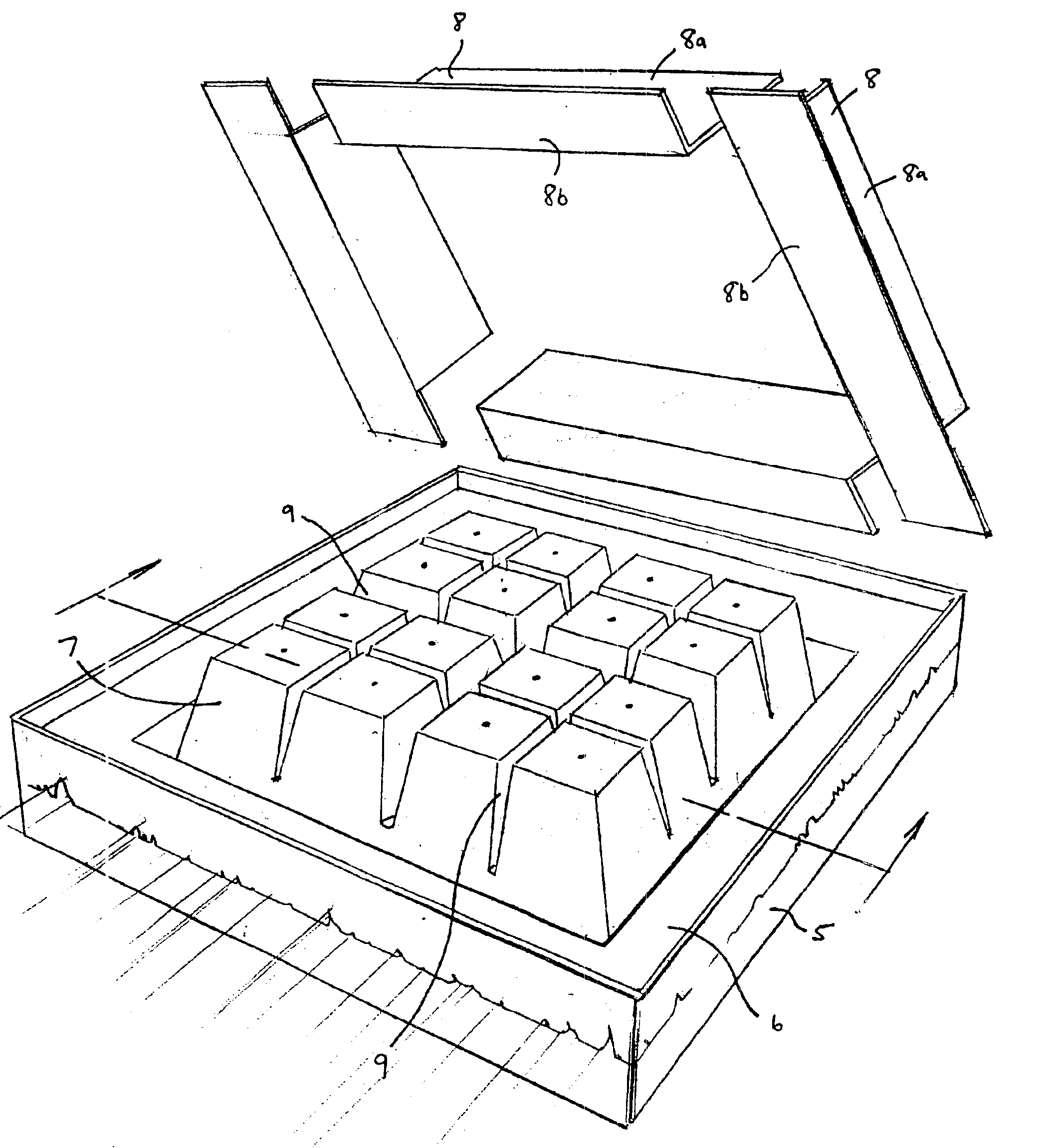
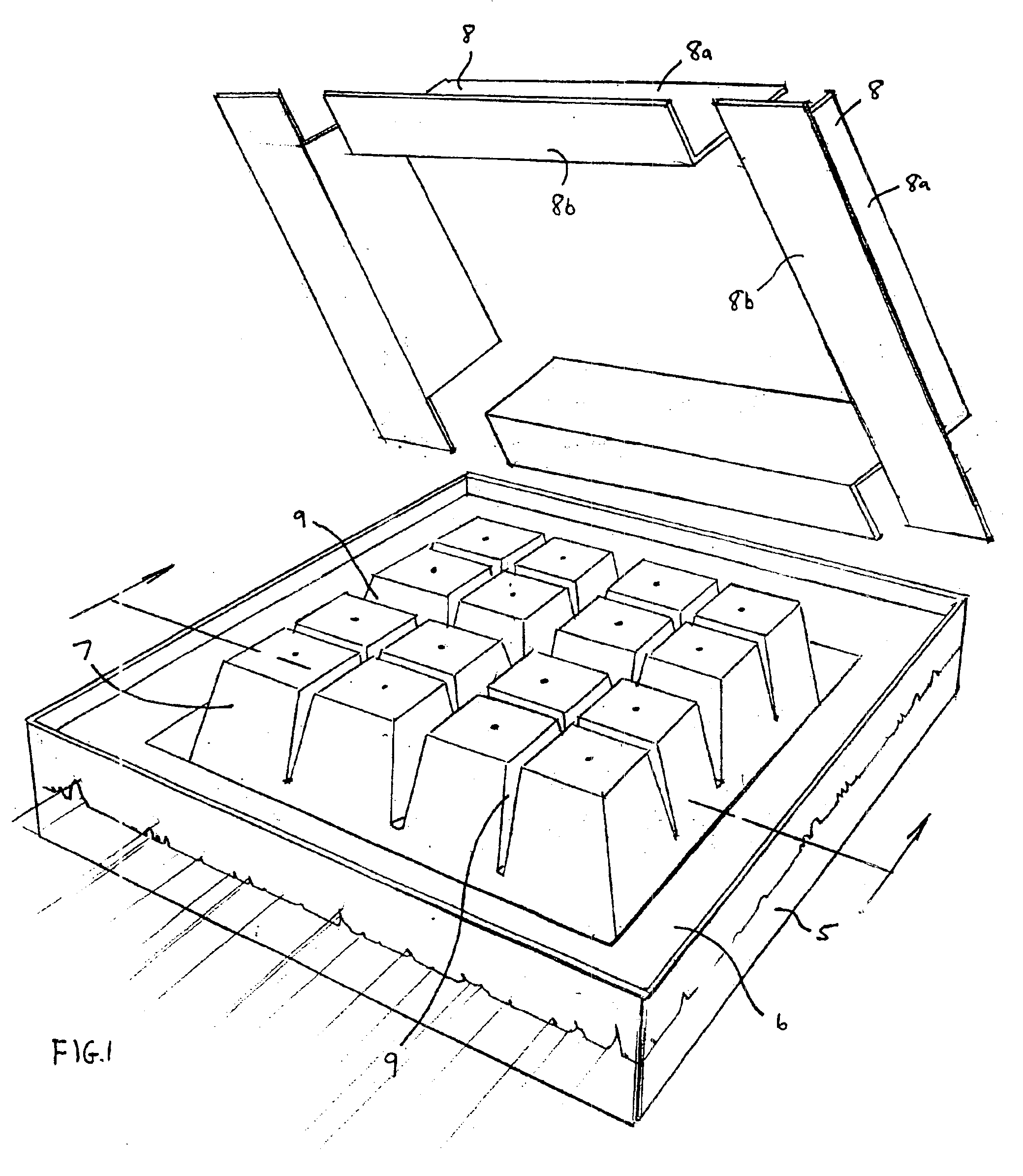
FIG. 1 is a perspective view of a floating platform 5, having a top surface 6 upon which a mold can be formed for constructing an anchor or other variable-buoyancy structure according to the present invention. Preferably, platform 5 itself has variable buoyancy, allowing it to be submerged and then re-floated. This variable buoyancy may be achieved by installing an array of ballast tanks (e.g., bolted to a series of trusses) underneath surface 6, e.g., in a manner similar to how a conventional dry dock is constructed.

As shown in FIG. 1, platform 5 has a generally flat top surface 6 upon which an array of forming cells 7 are attached, with a gap...


PUM


Abstract

Provided are a variety of variable-buoyancy structures, such anchors, together with methods and apparatuses for fabricating the same in the water. Generally speaking, such methods and apparatuses use a variable-buoyancy platform-based mold, initially floating, that includes multiple forming cells for fabricating the resulting variable-buoyancy structure. As a result, the variable-buoyancy structure produced has multiple corresponding structural cells having open bottoms. However, the structure may be fabricated so as to include a flexible or rigid container within some or all of such open-bottom cells.

Description

BACKGROUND OF THE INVENTION1. Field of the InventionThe present invention pertains to the fabrication of anchors and other structures having variable-buoyancy. As described in more detail below, the structures fabricated according to the present invention may be utilized in any of a wide variety of different maritime applications.2. Description of the Related ArtConventionally, the most common type of anchor is a solid anchor, typically formed from concrete. However, other types of anchors also have been proposed and / or used. One such alternative is an anchor having an internal cavity that may be filled with air to make the anchor buoyant, thereby facilitating the raising of the anchor when desired. Examples of such variable-buoyancy anchors are described in U.S. Pat. No. 4,290,381, titled “Floating Marina” (the '381 patent); U.S. Pat. No. 6,106,198, titled “Method for Installation of Tension-Leg Platforms and Flexible Tendon”; and U.S. Pat. No. 6,170,424, titled “Production / Platfor...

Claims


Application Information

Patent Timeline
IPC IPC(8): B63B35/44B63B35/00B63B21/22B63B21/26B63B21/50E02B3/06F03B13/18F03D11/04
CPCB63B21/22B63B35/00B63B35/44E02B3/062F03B13/1815F03D11/04F03D11/045B63B21/26Y02E10/727B63B21/502B63B2035/442B63B2035/446B63B2035/4466B63B2231/60F05B2240/93F05B2240/95F05B2240/97Y02E10/38F03D13/22F03D13/25Y02E10/30Y02E10/72Y02A10/11
Inventor DEMPSTER, HARRY EDWARD
Owner DEMPSTER HARRY EDWARD
Why Eureka
Try Eureka