Floating river debris skimmer

a technology of debris skimming and floating river, which is applied in water cleaning, water/sludge/sewage treatment, chemistry apparatus and processes, etc., can solve the problems of heavy debris tearing through, destroying the setup, and increasing the pollution of floating rivers and streams

Inactive Publication Date: 2005-03-01
JOHNSTON BARRY
View PDF14 Cites 17 Cited by
  • Summary
  • Abstract
  • Description
  • Claims
  • Application Information

AI Technical Summary

Benefits of technology

It is, therefore, an object of the present invention to provide a simple, inexpensice and easy-to-construct floating river debris skimmer which does not have, or at least lessens, the above mentioned problems. The rubble / trash skimmer's installer should be able to use commercially available devices such as swimming pool float dividers with minimal distraction to the natural landscape in constructing the skimmer.
It is another object of the present invention to provide a floating river debris skimmer which can rise and fall smoothly with the water level of the river and which does not obstruct waterway traffic along the river.
It is a further object of the present invention to provide a floating river debris skimmer which allows removal of light weight debris with ease, while passing heavier floating objects without destroying or damaging the skimmer.
It is yet another object of the present invention to provide a floating river debris skimmer line which, in practice, reliably breaks upon application of an excessive load caused e.g. by a heavy object travelling with the river current.
In accordance with another aspect of the present invention, a preferred embodiment of the pole vaults includes an elbow arm structure that would provide better leverage in shallower water. In particular, the arm of each pole vault may be provided with an elbow which allows the flow line to be partially lifted out of the water thus improving the leverage angle of the vaulting action so that the vaulting mechanism can continue to effectively lift the float line out of the water.

Problems solved by technology

Floating pollution on our rivers and streams increases dramatically with heavy rains and rising water levels.
Nets, stretching the length of the stream, have been used to collect the rubble but heavy debris tears through and destroys the setup.

Method used


Image

  • Floating river debris skimmer
  • Floating river debris skimmer
  • Floating river debris skimmer

Examples


Embodiment Construction

A floating river debris skimmer and a method of installing and using the floating river debris skimmer in accordance with the present invention are described. In the following detailed description, for purposes of explanation, numerous specific details are set forth in order to provide a thorough understanding of the present invention. It will be apparent, however, that the present invention may be practiced without these specific details. In other instances, well-known structures and devices are schematically shown in order to simplify the drawing.

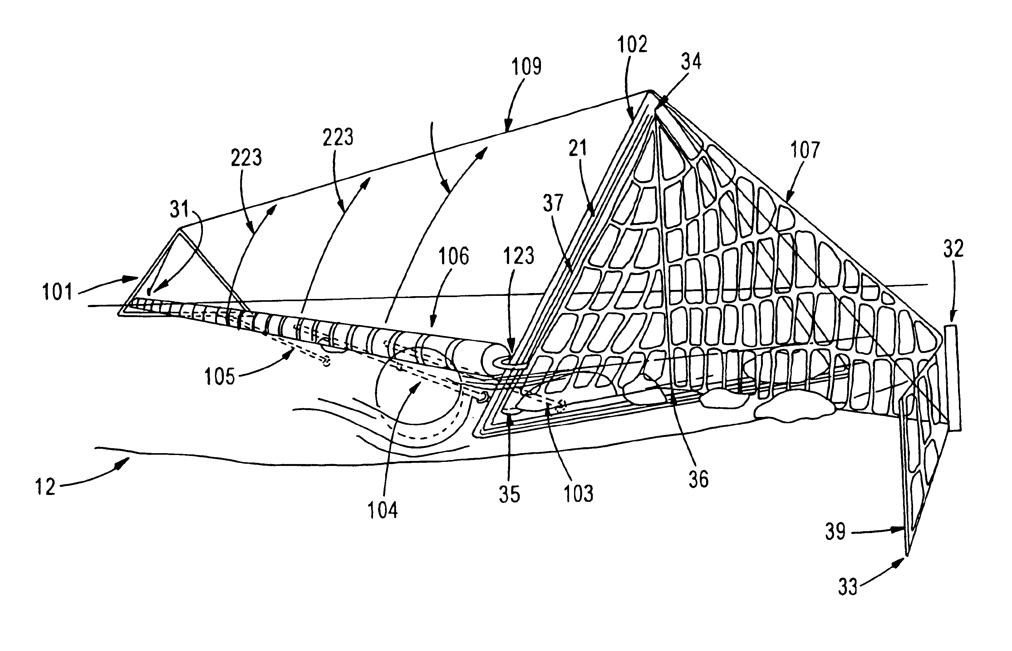
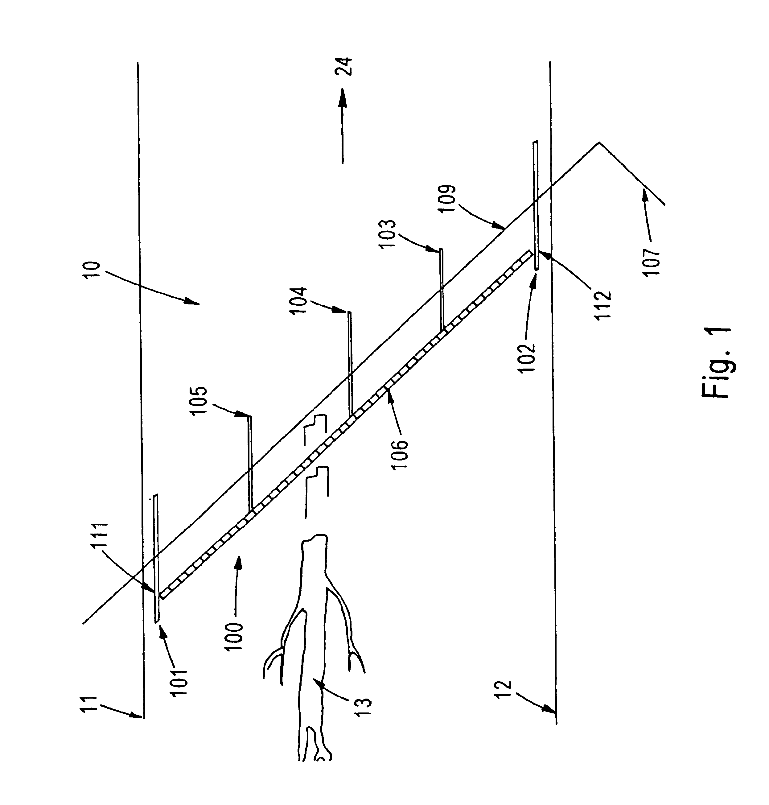
Referring now to FIG. 1, floating river debris skimmer 100 is shown. Skimmer 100 includes float line 106 installed across river 10 at an angle with respect to flowing direction 24 of the river. Skimmer 100 further includes two supports 101, 102 installed near the river bank edges 11, 12, respectively. As can be seen in FIG. 1, supports 101, 102 are attached to upstream and downstream ends 111, 112 of float line 106, respectively. The ends...


PUM


Abstract

A skimmer for removing debris off the surface of a river includes a float line installed across the river at an angle with respect to the river current, and a collecting net installed at the downstream end of the float line. The ends of the line are slidable upwards, along inclined supports, to unsnag the line when a heavy object hooks onto the line. A second mechanism, assisting in raising the line, is a series of rods which swivel in a pole-vaulted fashion from their leverage at the bottom of the river to lift the line out of the water and allow the heavy object to pass underneath. If the object hits the line with an excessive force, the line will reliably break at a desired weak point. The rods may have elbow joints that would provide better leverage in shallow water.

Description

TECHNICAL FIELDThe present invention generally relates to floating river debris skimmers. More particularly, the present invention relates to a floating river debris skimmer having a float line obliquely installed across the river and a mechanism for assisting in lifting the float line, at least partially, out of the water.BACKGROUND OF THE INVENTIONFloating pollution on our rivers and streams increases dramatically with heavy rains and rising water levels. Nets, stretching the length of the stream, have been used to collect the rubble but heavy debris tears through and destroys the setup. It has been known to include a line of steel baskets jointed as a collector net to catch the trash. This basket system supposedly will endure the abuse of the heavy debris.Therefore, there is a need for an apparatus for and method of collecting the floating debris in a netted area at one of the banks where it can easily be collected. The heavy rubble, such as floating logs, will pass without damag...

Claims


Application Information

Patent Timeline
Patent Type & Authority Patents(United States)
IPC IPC(8): E02B15/04E02B8/00E02B8/02
CPCE02B8/023E02B15/0835E02B15/0807E02B15/06
Inventor JOHNSTON, BARRY
Owner JOHNSTON BARRY
Why Eureka
Try Eureka