
Carpal tunnel splint for wear during non-working periods

a carpal tunnel and non-working technology, applied in the field of body supports, can solve the problems of numbness in the wrist and hand, tingling or burning sensation, scratching the wearer, etc., and achieve the effect of relieved pressure on the median nerve and easy pulling

Inactive Publication Date: 2005-03-01
CHOW JAMES C Y
View PDF14 Cites 2 Cited by
  • Summary
  • Abstract
  • Description
  • Claims
  • Application Information

AI Technical Summary

Benefits of technology

A carpal tunnel splint of the present invention includes a sleeve open at one end to fit over a person's hand and wrist. The other end of the sleeve has thumb and finger holes formed in it so the sleeve can be readily pulled on. The splint is worn during non-work periods and bedtime when the wearer needs a more neutral support that allows them to readily perform a wide range of activities. The support provided by the splint is adjustable to provide a level of comfort and support to the wearer which differs from that provided by the splint worn when the person is working. The splint is made of a lightweight material which fits easily underneath the person's clothing if so desired. When worn, the splint supports the wrist and relieves pressure on the median nerve. When the person goes to work, they replace the splint with one designed for the work they do. Other objects and features will be in part apparent and in part pointed out hereinafter.

Problems solved by technology

The resulting injury causes numbness in the wrist and hand at some times, and a tingling or burning sensation at others.
Second, many splints worn during working periods have straps, belts, or the like which secure the splint in place.
However, if worn to bed, these straps and belts can scratch the wearer causing injury.
Or, the wearer may subconsciously remove the splint, aggravating their injury.
Third, in industrial settings, and even in some office environments, the splint worn during working hours can get very dirty because of the type of work the wearer does.
Wearing the splint at other times can therefore be unsanitary as well as unsightly.

Method used


Image

  • Carpal tunnel splint for wear during non-working periods
  • Carpal tunnel splint for wear during non-working periods
  • Carpal tunnel splint for wear during non-working periods

Examples


Embodiment Construction

The following detailed description illustrates the invention by way of example and not by way of limitation. This description will clearly enable one skilled in the art to make and use the invention, and describes several embodiments, adaptations, variations, alternatives and uses of the invention, including what I presently believe is the best mode of carrying out the invention. As various changes could be made in the above constructions without departing from the scope of the invention, it is intended that all matter contained in the above description or shown in the accompanying drawings shall be interpreted as illustrative and not in a limiting sense.

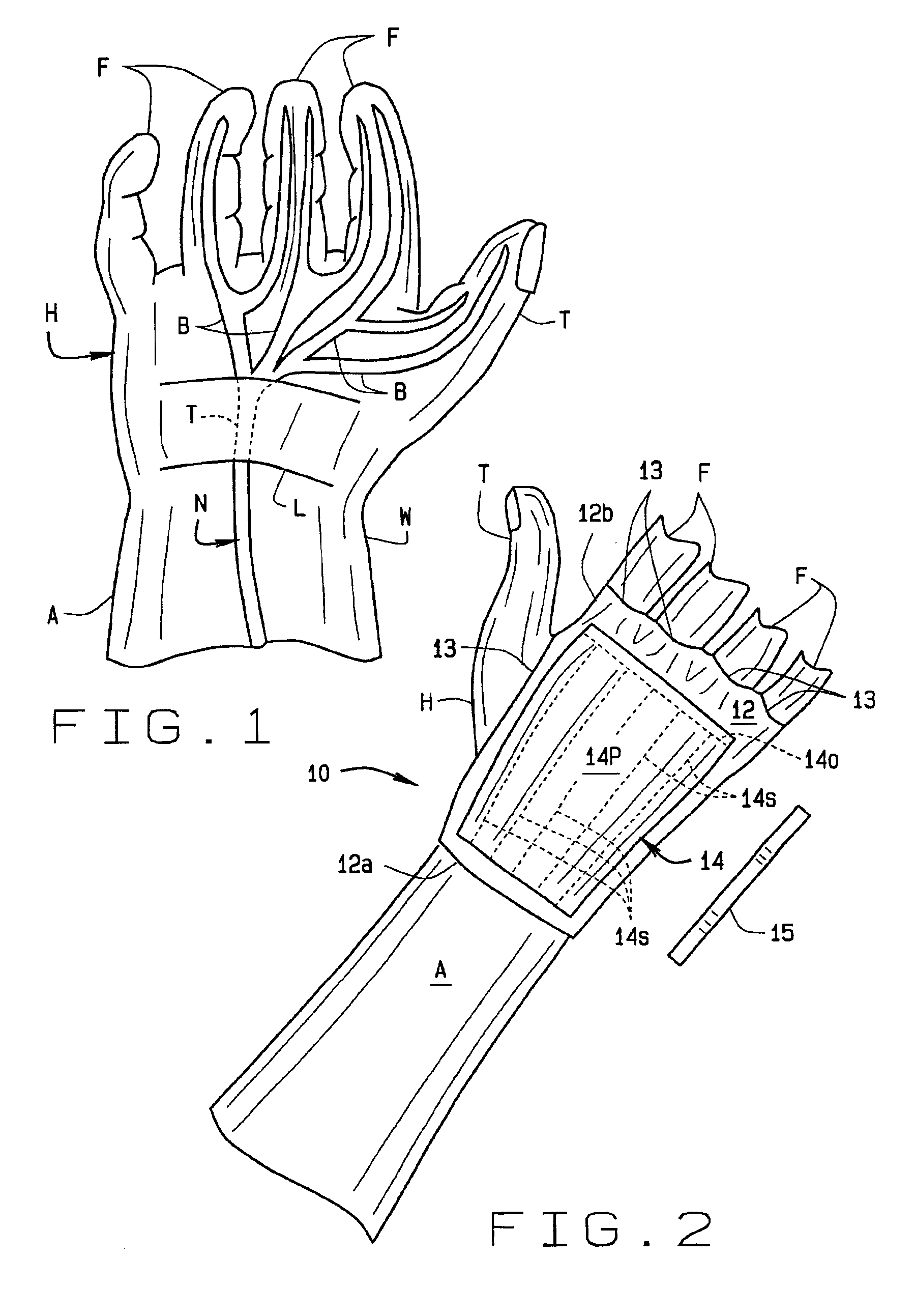
Referring to the drawings, a splint 10 of the present invention is for use in the treatment of carpal tunnel syndrome, the cause of which has been previously described. The splint of the present invention includes a sleeve 12 which over the person's hand H and extends up their arm A past their wrist W. Sleeve 12 is of a lightweight,...


PUM


Abstract

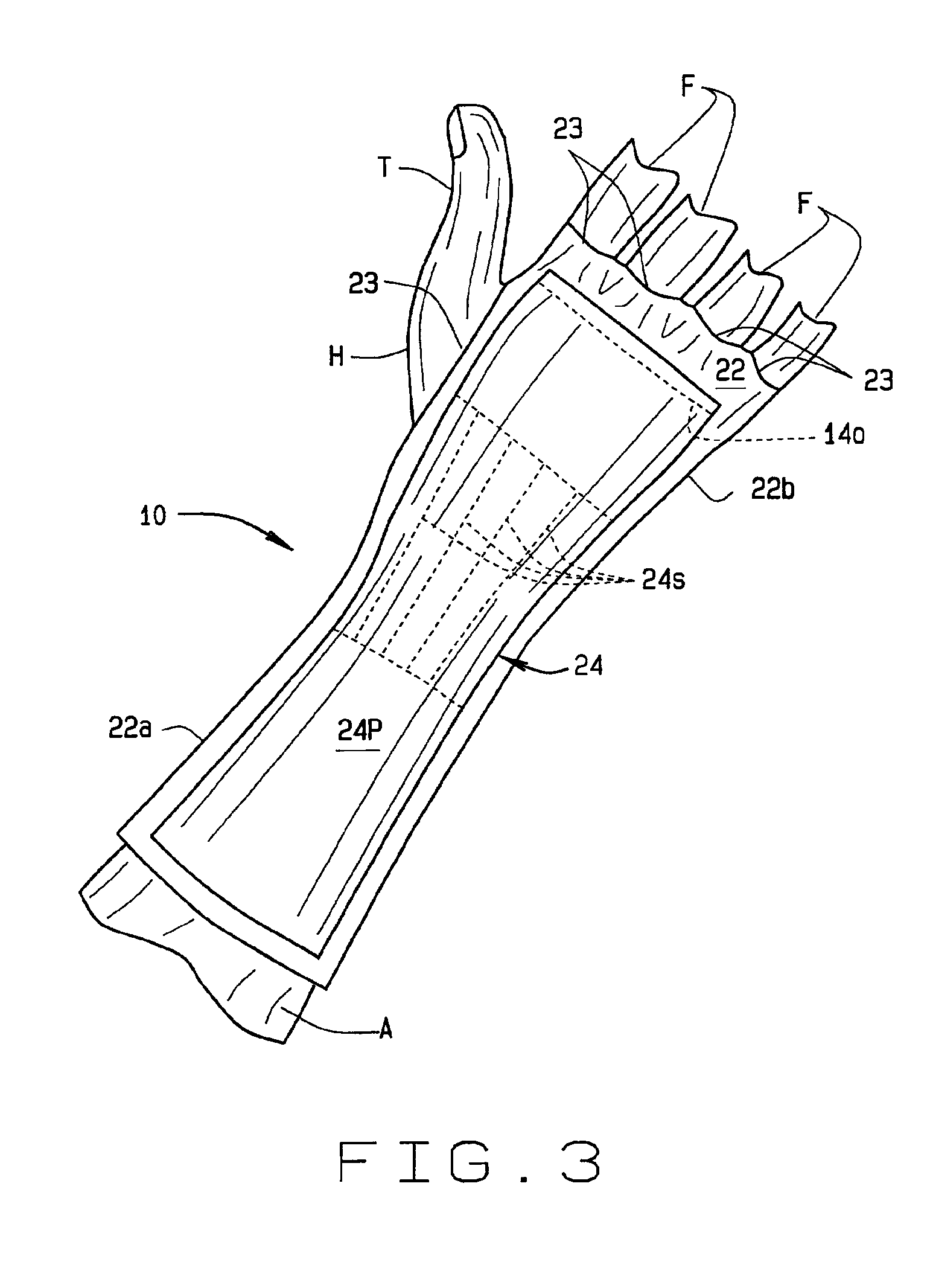
A splint (10) worn by a sufferer of carpal tunnel syndrome. A first sleeve (12) fits over the person's hand (H) and extends up their arm (A) past their wrist (W). This sleeve is worn during non-working portions of the person's day and includes a support (14) formed in the palm portion of the sleeve to support the carpal tunnel and relieve pressure on the median nerve passing through it. This alleviates pain caused by carpal tunnel syndrome. A second sleeve (22) also fits over the person's hand and extends up their arm past their wrist. This second sleeve, which is also worn during non-working portions of the day, extends further up the person's arm than the first sleeve. A support (24) of this second sleeve extends along the back of the person's hand to also relieve pressure on the median nerve and alleviate the pain caused by carpal tunnel syndrome.

Description

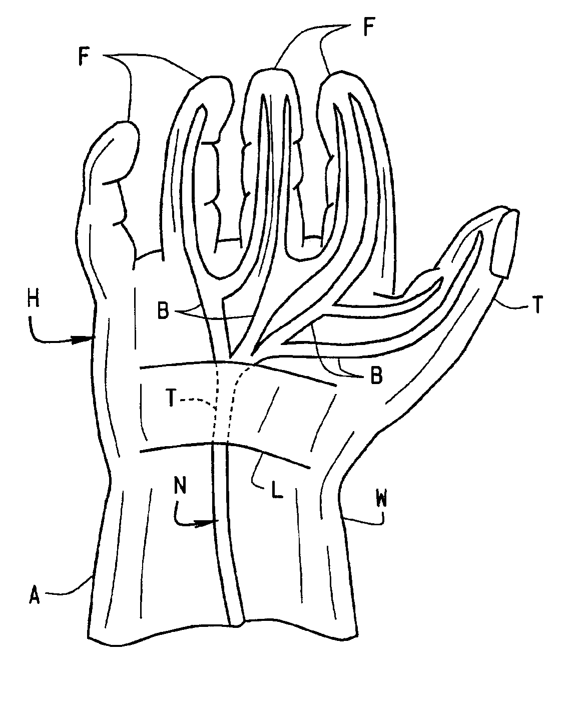
CROSS REFERENCE TO RELATED APPLICATIONSSTATEMENT REGARDING FEDERALLY SPONSORED RESEARCH OR DEVELOPMENTBACKGROUND OF THE INVENTIONThis invention relates to body supports, and more particularly to a splint worn on the hand and wrist by someone suffering from carpal tunnel syndrome. The splint is for use during non-working periods in which support of the wrist and treat the carpal tunnel syndrome.Carpal tunnel syndrome is a condition resulting from a compression of the median nerve as it passes through the carpal tunnel portion of a person's wrist and hand. As shown in FIG. 1, the median nerve N carries sensations to and from a person's fingers F and powers movement of the person's thumb T. The nerve extends through the wrist W, and then has branches B extending to the fingers and thumb. A transverse carpal ligament L formed at the base of the hand H extends from one side of the hand, across the base of the palm of the hand, to the other side of the hand. The carpal tunnel T comprises ...

Claims


Application Information

Patent Timeline
IPC IPC(8): A61F13/10A61F5/01
CPCA61F13/10A61F5/0118
Inventor CHOW, JAMES C. Y.
Owner CHOW JAMES C Y
Learn More