
Back wire ground clamp

a ground clamp and back wire technology, applied in the direction of connection contact member materials, electrical apparatus casings/cabinets/drawers, coupling device connections, etc., can solve the problems of relatively high manufacturing cost and general complexity of the arrangement of the ground clamping plate disclosed in the prior ar

Active Publication Date: 2005-03-01
LEVITON MFG
View PDF8 Cites 13 Cited by
  • Summary
  • Abstract
  • Description
  • Claims
  • Application Information

AI Technical Summary

Benefits of technology

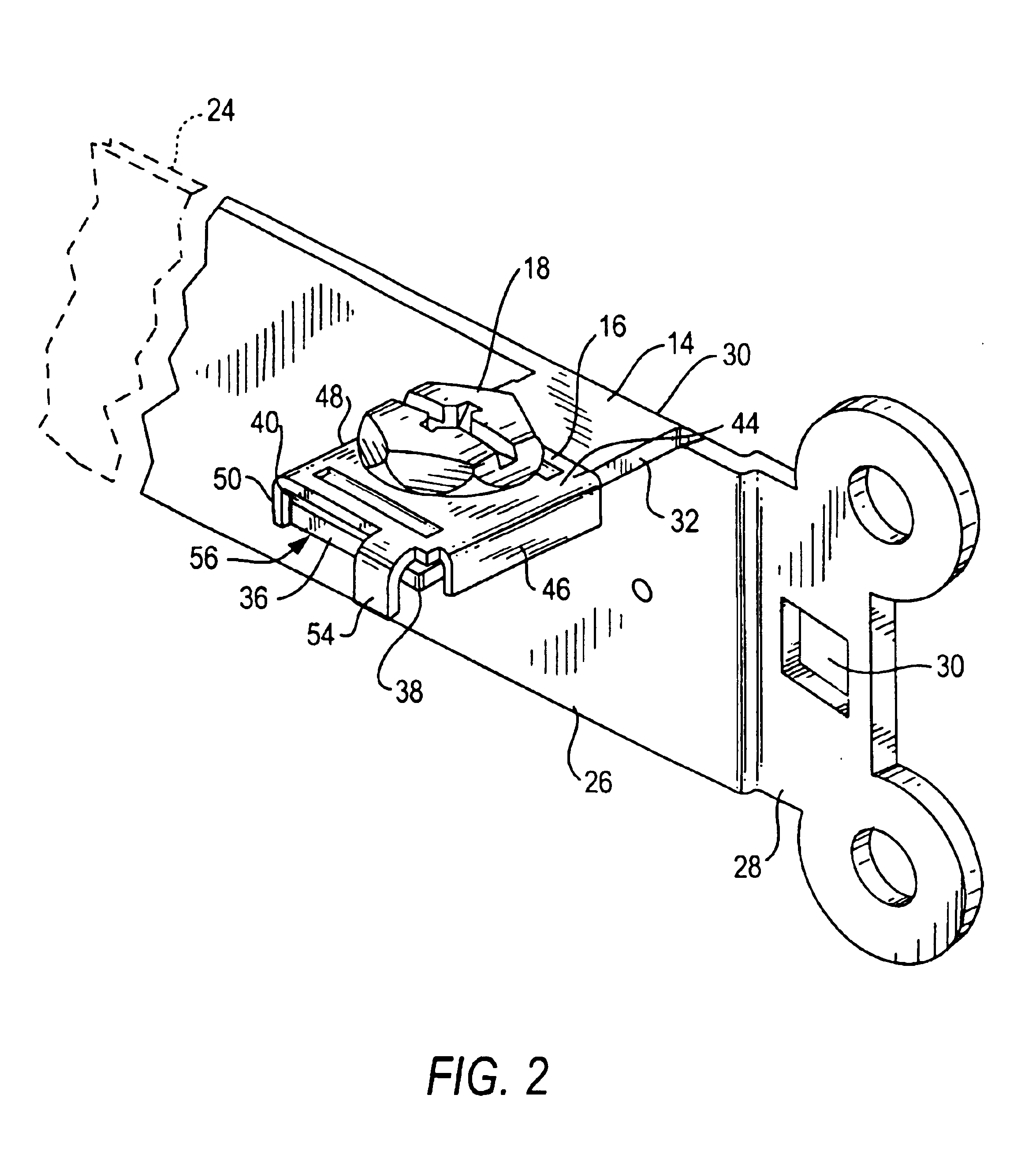
The invention here disclosed is a back wire ground clamp for a wiring device such as a switch or receptacle having a ground strap which supports an outwardly projecting ground lug having a front edge and adapted to receive a ground connection. The ground lug is coupled to a clamp plate by means of a screw which passes through a clearance opening in the clamp plate and is threaded into a receiving opening in the ground lug. The clamp plate supports a blocking tab which extends downward below the front edge of the ground lug and extends side ways for a distance which is less than the length of the front edge of the ground lug. The blocking tab prevents the clamp plate from rotating relative to the ground lug as the screw is tightened and defines an opening between the clamp plate and the ground lug along the front edge of the ground lug into which a single ground wire can be inserted.

Problems solved by technology

The clamping plate arrangements disclosed in the prior art are generally complex in shape and relatively expensive to manufacture.

Method used


Image

  • Back wire ground clamp
  • Back wire ground clamp
  • Back wire ground clamp

Examples


Embodiment Construction

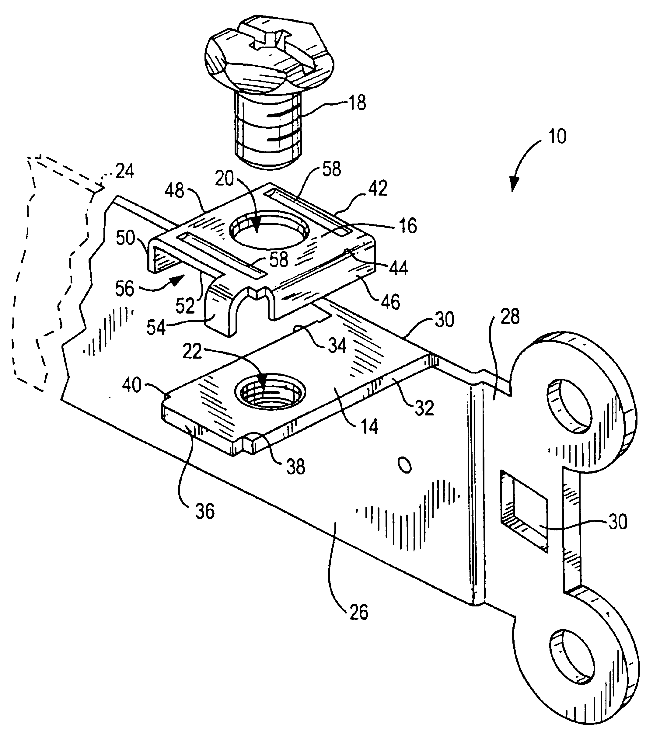
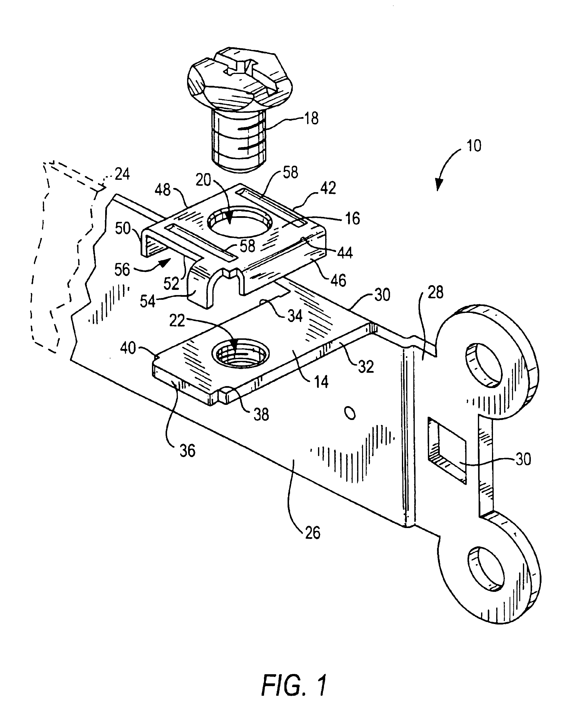
Referring to FIG. 1, a back wire ground clamp 10 according to an embodiment of the invention consists of a ground strap 12 having a ground lug 14 which is adapted to be engage by a clamp plate 16 having a substantially rectangular flat plate that supports three tabs. The tabs extend outward at right angles to the flat plate and are arranged to engage two side edges and a front edge of the ground lug. A screw 18, which extends through a clearance opening 20 in clamp plate 16, is provided to engage a screw threaded opening 22 in ground lug 14.

In the embodiment here shown the ground strap supports the ground lug 14 to provide the ground connection for an electrical switch or an electrical receptacle. An electrical ground connection is made by connecting a ground wire to the ground strap. The invention here disclosed can bb used for any contact member of a receptacle or a switch, but the invention is particularly well adapted for use as a ground clamp on a switch or receptacle that is b...


PUM


Abstract

The invention here disclosed is a back wire ground clamp for a wiring device such as a switch or receptacle having a ground strap which supports an outwardly projecting ground lug having a front edge and adapted to receive a ground connection. The ground lug is coupled to a clamp plate by means of a screw which passes through a clearance opening in the clamp plate and is threaded into a receiving opening in the ground lug. The clamp plate supports a blocking tab which extends downward below the front edge of the ground lug and extends side ways for a distance which is less than the length of the front edge of the ground lug. The blocking tab prevents the clamp plate from rotating relative to the ground lug as the screw is tightened and defines an opening between the clamp plate and the ground lug along the front edge of the ground lug into which a single ground wire can be inserted.

Description

BACKGROUND OF THE INVENTION1. Field of the InventionThis invention relates generally to electrical wiring devices such as electrical switches, receptacles and the like and more particularly to a clamp for back wiring a ground wire to a ground strap.2. Description of the Prior ArtElectrical switches and receptacles that are used in homes, offices and factories have terminals to which electrical wires are connected by turning a screw down on the wire. The electrical wire is usually a relatively stiff solid wire that must first be shaped into a loop to fit around the mounting screw and then the mounting screw is screw down. The bending of the wire takes time and, if the loop is placed under the screw where the loop is positioned to be turning in a counter-clockwise direction rather than in a clockwise direction, the loop will tend to open up and move out from under the head of the screw as the screw is tightened in a clockwise direction. Additionally, in many instances it is faster and...

Claims


Application Information

Patent Timeline
IPC IPC(8): H01H9/12H01H9/00H01R13/648H01R4/28H01R4/30H01R4/34
CPCH01H9/12H01R13/648H01R4/34H01R4/305
Inventor GREENE, JEFFTUFANO, ANTHONYBALABAN, DAVID B.
Owner LEVITON MFG
Learn More