Integrated switch and backlight assembly

a switch and backlight technology, applied in the direction of contact surface shape/structure, emergency actuators, contact surfaces, etc., can solve the problem that it is not practical to backlight keypads with conductive contacts using fiber optic panels, and achieve the effect of more reliable, cost-effective and thin

Active Publication Date: 2005-03-01
LUMITEX
View PDF12 Cites 41 Cited by
  • Summary
  • Abstract
  • Description
  • Claims
  • Application Information

AI Technical Summary

Benefits of technology

[0005]The present invention relates to a switch and backlight assembly including a light emitting panel that is

Problems solved by technology

Heretofore it wasn't practical to backlight keypads with conductive contacts using fiber optic panels because the fib

Method used


Image

  • Integrated switch and backlight assembly
  • Integrated switch and backlight assembly
  • Integrated switch and backlight assembly

Examples


Embodiment Construction

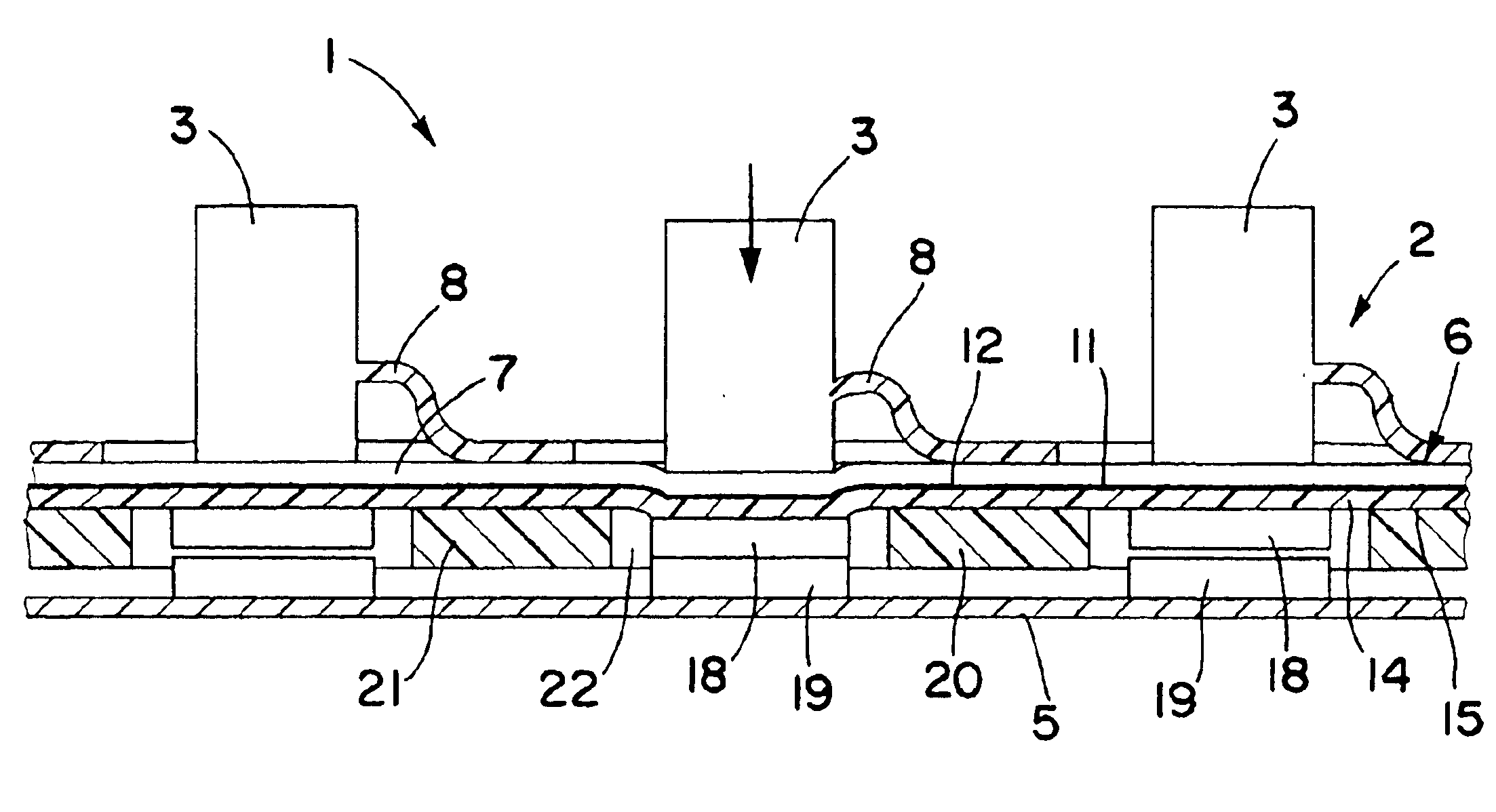
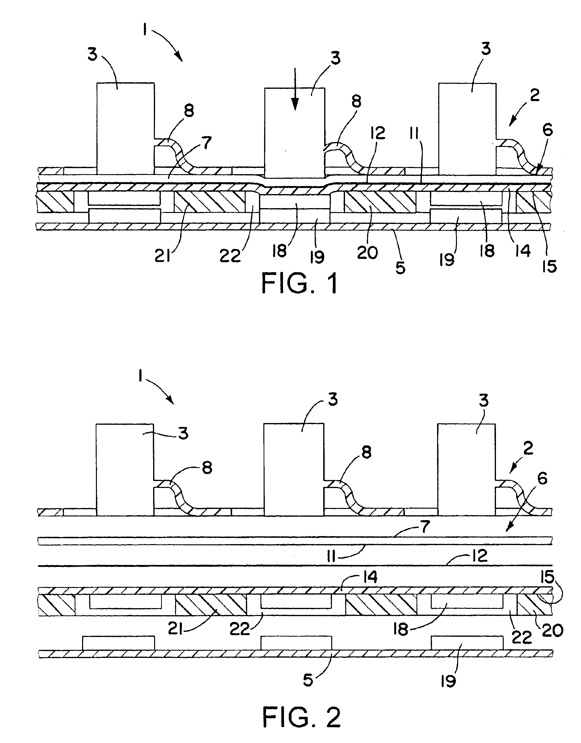
[0015]Referring now in detail to the drawings, FIGS. 1 and 2 schematically show a portion of an integrated switch and backlight assembly 1 in accordance with the invention, including a keypad 2 having a plurality of keys 3 which when selectively actuated activate respective switch contacts associated with each of the keys as described hereafter. Upon release of the keys, the keys return to their original positions.

[0016]Spaced from keypad 2 is a circuit board 5 having a desired conductive trace thereon. Between the keypad 2 and circuit board 5 is a flexible light conducting panel member 6 that receives light from one or more light sources (not shown) for emission of the light at selective locations along the length of the panel member for backlighting the keys, as well known in the art. Panel member 6 may comprise one or more layers of flexible optical fibers 7. Alternatively, panel member 6 may comprise a flexible optically transparent film, sheet or plate as desired.

[0017]The keys...


PUM


Abstract

Integrated switch and backlight assembly includes a flexible light panel disposed between a circuit board and a keypad for backlighting the keypad. On the back side of the light panel is a back reflector having a plurality of contacts for selectively establishing electrical contact with the circuit board upon actuating selective portions of the keypad to cause corresponding portions of the light panel and back reflector to flex toward the circuit board.

Description

FIELD OF THE INVENTION[0002]This invention relates to a switch and backlight assembly in which the backlight is integrated into the switch to provide a more cost effective and thinner switch / backlight assembly.BACKGROUND OF THE INVENTION[0003]Fiber optic light panels are commonly used to backlight dome type membrane switches and the like. The light panel is placed between the domes and a semi-transparent or translucent overlay. When the overlay is depressed, the light panel is selectively deflected into contact with respective domes, causing electrical contact to be made between the domes and conductive contacts on a circuit board underlying the domes.[0004]Keypads with conductive contacts adhered to respective keys are also commonly used to make electrical contact with conductive contacts on a circuit board to activate respective switches. Heretofore it wasn't practical to backlight keypads with conductive contacts using fiber optic panels because the fiber optic panels interfered ...

Claims


Application Information

Patent Timeline
IPC IPC(8): H01H13/702
CPCH01H13/702H01H2219/06H01H2219/062H01H2221/002
Inventor SCHULZ, WALTER B.PAGE, DAVID J.
Owner LUMITEX
Why Eureka
Try Eureka