System for passive and stable suspension of a rotor in rotor/stator assemblies

a technology of rotor/stator assembly and suspension system, which is applied in the direction of machines/engines, prosthesis, liquid fuel engines, etc., can solve the problems of poisonous fluids, unstable negative force in one plane or along an axis, and become extremely dangerous

Inactive Publication Date: 2005-03-01
ADVANCED BIONICS INC
View PDF23 Cites 23 Cited by
  • Summary
  • Abstract
  • Description
  • Claims
  • Application Information

AI Technical Summary

Benefits of technology

Therefore, it is a primary object of the present invention to provide a passive and stable suspension of a rotor utilizing magnetic or electrostatic forces applied relative to a reference frame.
It is a further object of the present invention to provide a stable suspension of a rotor within a stator with positive stiffness in all five degrees of freedom, excepting in the sixth degree of freedom which is defined as a rotation around or about the axis of rotation of the rotor when a torque is applied.
It is a further object of the present invention to provide a passive and stable suspension of a rotor within a stator utilizing inertial dynamic interaction between the rotor and a fluid medium in which the rotor rotates to create positive stiffness in all five degrees of freedom of the rotor.
Yet a further object of the present invention is to provide a passive and stable suspension of the rotor incorporating passive permanent magnetic bearings and dynamic interaction between the rotor and a fluid medium in which the rotor is rotating for use in a variety of applications.
It is a further object of the present invention to provide a novel passive and stably suspended rotor in a one of a kind mechanism employing a rotor confined within a stator, and wherein stability is achieved through rotation of the rotor.

Problems solved by technology

The magnetic components may be designed in a variety of different coupling arrangements, with passive magnetic bearings being employed for creating stability along certain selected planes or axes and further creating one resultant unstable negative force in one plane or along an axis.
Passive magnetic forces are applied to the rotor during periods of rotation and dwell, with these passive forces including a resultant unstable negative force in a plane or along an axis perpendicular to the axis of rotation.
Poisonous fluids, for example, become extremely dangerous whenever leakage develops, a common consequence of bearing failure.

Method used


Image

  • System for passive and stable suspension of a rotor in rotor/stator assemblies
  • System for passive and stable suspension of a rotor in rotor/stator assemblies
  • System for passive and stable suspension of a rotor in rotor/stator assemblies

Examples


Embodiment Construction

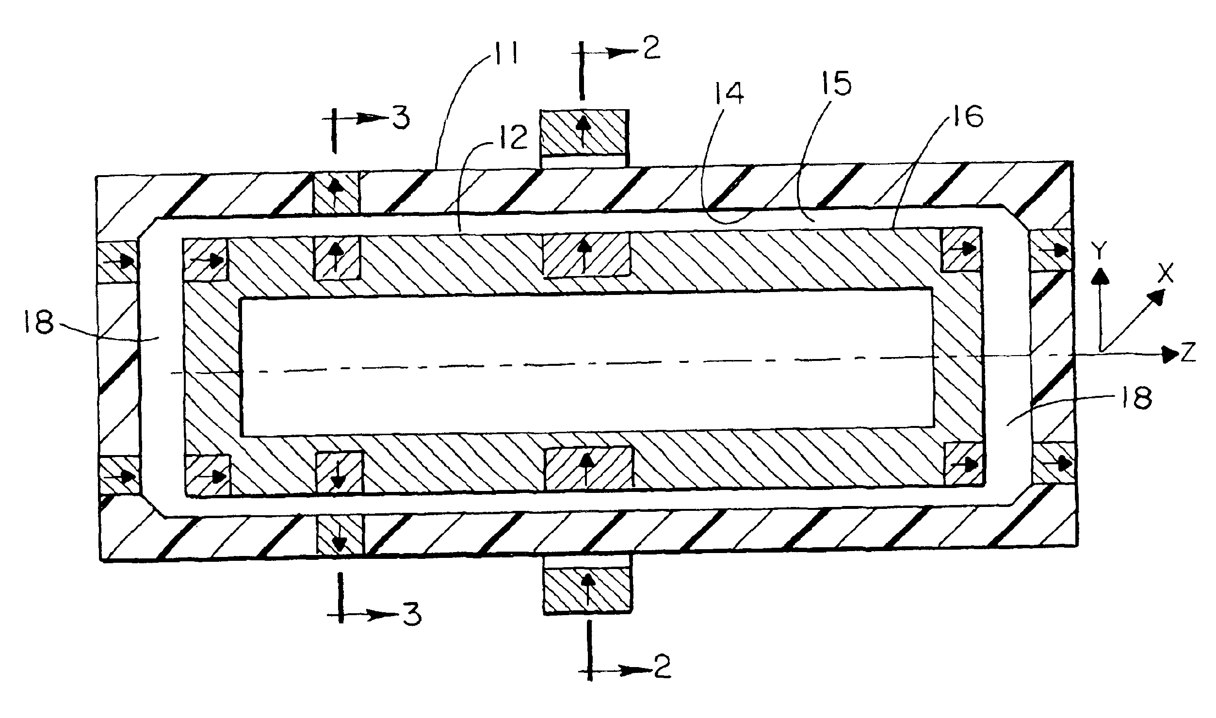
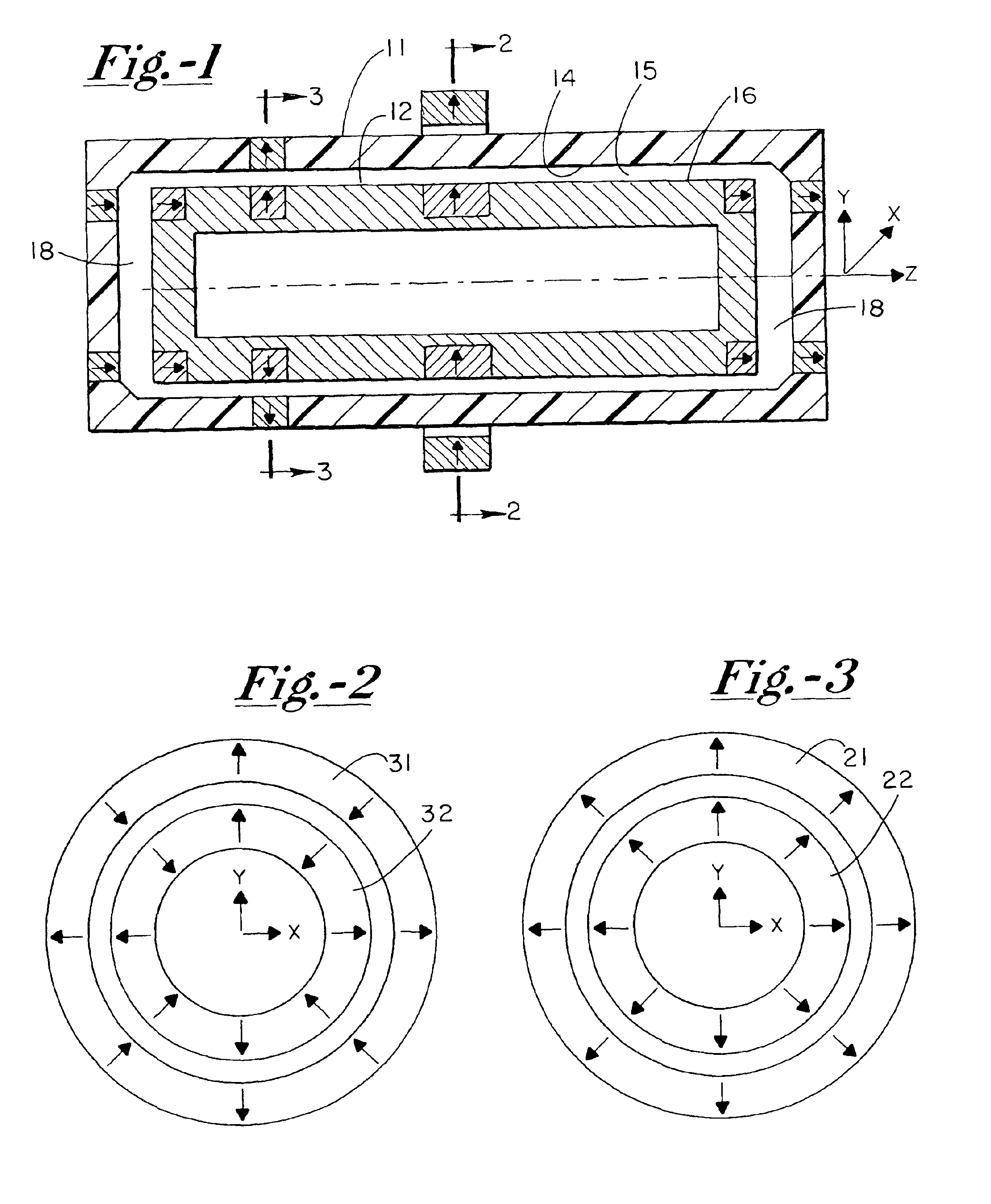
With reference to the device illustrated in FIG. 1, the system generally designated 10 comprises a shell or housing 11 along with a rotor structure 12. Body 11 has an inner wall 14 which defines the chamber zone 15 therewithin. Rotor 12 has an outer surface as at 16 which is spaced from wall 14, thereby configuring chamber zone 15 into an annular zone. End zone openings 18—18 are provided which comprise faces or bases. The zones 15 and 18—18 are normally filled with media or fluid as indicated in FIG. 1. Rotor body 11 has six degrees of freedom in a Cartesian coordinate system, these degrees of freedom being manifested in forces delivered along coordinate axes and rotation about these axes.

The origin of the system is located in the geometrical center of the rotor 12. In rotor 12, one degree of freedom is preserved for rotation about the Z axis. Support of rotor 12 is provided, with the support having the positive stiffness in each of the other five degrees of freedom, with “positive...


PUM


Abstract

A rotary mechanism includes a stator body defining a chamber and an elongated rotor operationally disposed within the chamber. The elongated rotor has opposed ends with a central axis defining an axis of rotation, with magnetic driven elements disposed on the rotor and positioned outwardly of the rotor axis between the opposed ends. Passive magnetic bearing pairs are positioned along opposed ends of the rotor body with each bearing pair being similarly polarized so as to be in mutually attracting or mutually repelling relationship. A third passive magnetic bearing pair is positioned along the rotor axis between the opposed ends with the third bearing pair being magnetically coupled similarly to the first and second bearing pairs, with the passive magnetic bearings creating an unstable negative force in a plane perpendicular to the axis of rotation of the rotor with the negative stiffness being overcome upon rotation of the rotor creating a centrifugal force of a magnitude greater than that of the unstable negative force.

Description

BACKGROUND OF THE INVENTIONThe present invention relates generally to a novel suspension system for the rotor component in a rotor / stator assembly, and more particularly to such a system which provides for passive and stable suspension of the rotor. Assemblies utilizing the features of the present invention are adapted for a wide variety of applications, including fluid handling systems for fragile or aggressive fluids, as well as for other applications pertaining to instrumentation, as well as applications for such assemblies which may be characterized as either delicate and / or rugged. The novel passive and stable suspension system of the present invention includes a rotor which is typically suspended within a stator, with the rotor being stabilized through passive magnetic as well as hydrodynamic forces.The magnetic components may be designed in a variety of different coupling arrangements, with passive magnetic bearings being employed for creating stability along certain selected...

Claims


Application Information

Patent Timeline
Patent Type & Authority Patents(United States)
IPC IPC(8): A61M1/10F16C39/00F16C39/06F04D13/06F04D29/04F04D3/00H02N15/00A61M60/178A61M60/232A61M60/419A61M60/422A61M60/818A61M60/82F04D29/048
CPCA61M1/101F04D3/00F04D29/048F16C32/041A61M1/1017H02N15/00F04D13/0633F04D13/064A61M1/1015F16C32/0423F16C2316/18A61M60/824A61M60/422A61M60/148A61M60/419A61M60/232A61M60/178
Inventor IZRAELEV, VALENTIN M.
Owner ADVANCED BIONICS INC
Why Eureka
Try Eureka