Frequency conversion sweep measuring method

a sweep measurement and frequency conversion technology, applied in the field of measurement, can solve the problems of filtering response, impractical to provide impracticality of providing so many external filters,

Inactive Publication Date: 2005-03-01
ADVANTEST CORP
View PDF9 Cites 21 Cited by
  • Summary
  • Abstract
  • Description
  • Claims
  • Application Information

AI Technical Summary

Benefits of technology

It is an object of the present invention to provide a method of measurement by sweeping frequency conversion which enables a correct measurement without the provision of a preselector while avoiding an influence of image signals if measured data for a plurality of signals occur at a same measured frequency point.

Problems solved by technology

The YIG variable tuning filter 16 has a good filtering response, but is expensive and bulky.
It is impractical to provide so many external filters 202.
However, it is to be noted that such YIG tuning filter 204 itself represents a very expensive component, and may cost as much as comparable to the apparatus proper.
This resulted in a high cost.
However, with three channels of frequency converters, there exist a number of circuit blocks, thus requiring a number of shielded spaces.
As a consequence, the cost of the apparatus increases in proportion to the circuit blocks and the circuit elements.
The provision of a number of shielded spaces result in a casing of an increased size, rendering it difficult to reduce the size and the weight.
However, a correct measurement is only possible under the condition that a signal being measured which is input as well as a spurious signal which is generated within the measuring apparatus do not appear at an image frequency point or at FN5a, FN5c as considered in FIG. 5, during the frequency sweep.

Method used


Image

  • Frequency conversion sweep measuring method
  • Frequency conversion sweep measuring method
  • Frequency conversion sweep measuring method

Examples


first embodiment

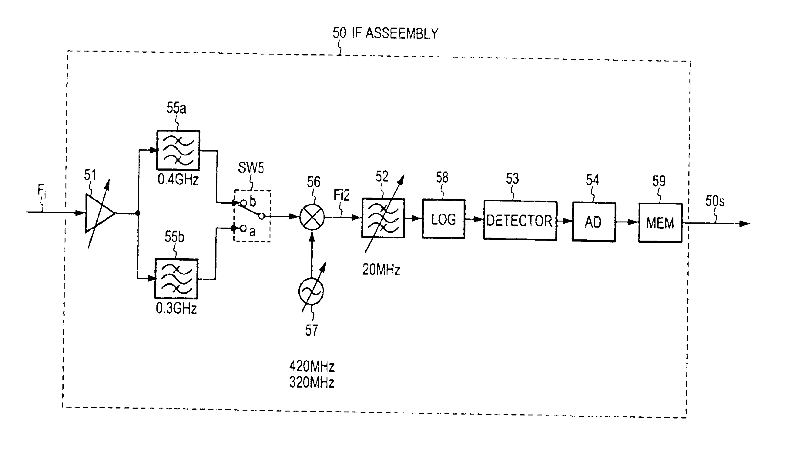
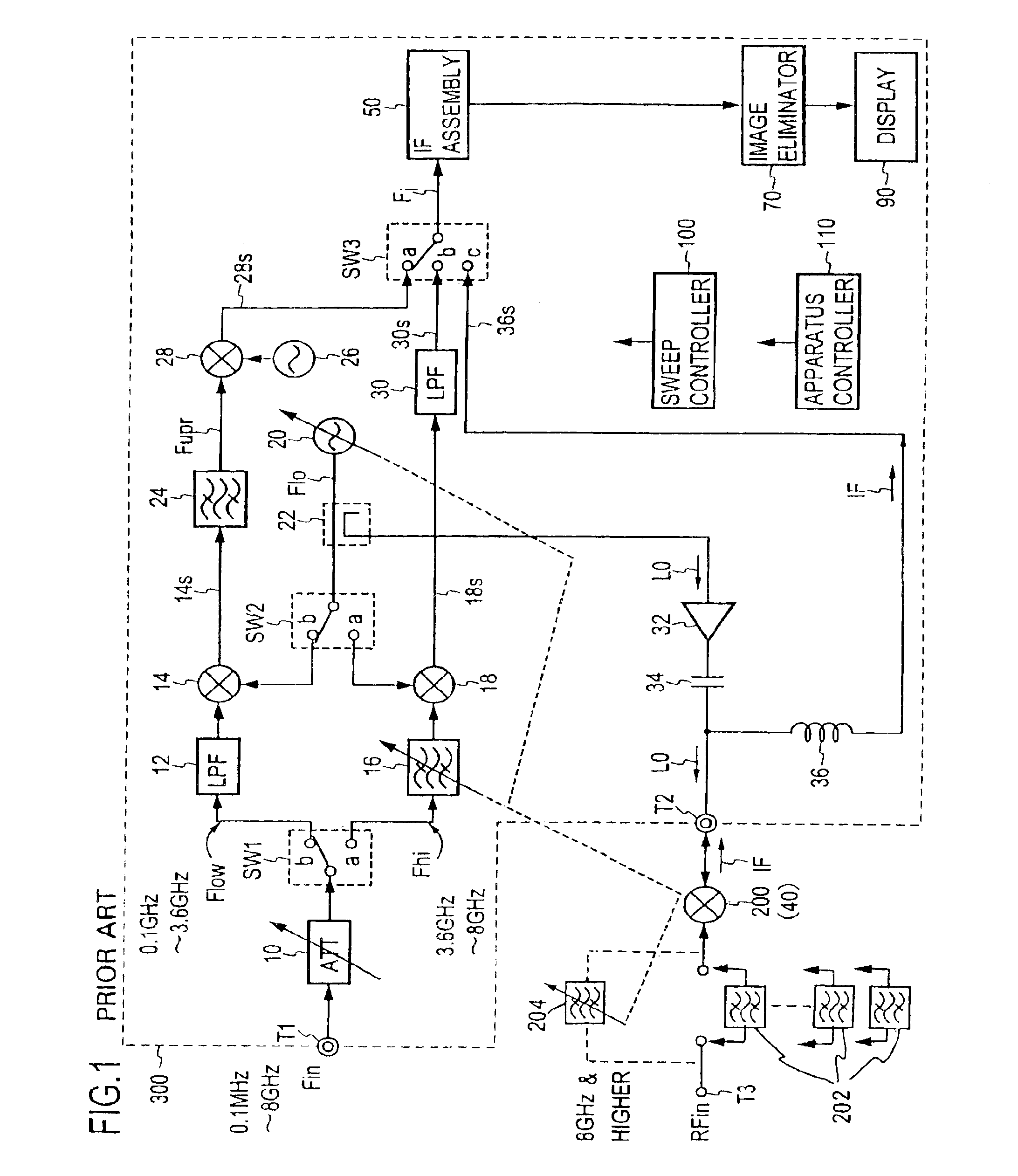
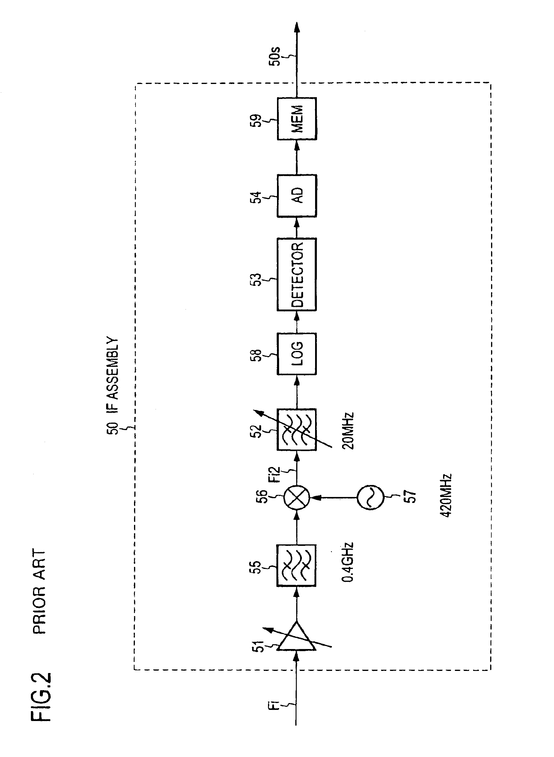
The application of an embodiment of the present invention to a spectrum analyzer will be described. FIG. 7 shows an embodiment of a spectrum analyzer in which the present invention is applied, and corresponding parts to those shown in FIG. 1 are designated by like reference characters as used before.

A signal being measured is fed from an input terminal T1 through a variable attenuator 10 which renders it to be within a given range of levels, as required, to a mixer 40. It is to be noted that there is no preselector which acts upon the signal being measured. A frequency sweep signal is input as a local signal from a sweep oscillator 20 to the mixer 40. The mixer 40 may be a harmonic mixer which frequency mixes the signal being measured, not only with a fundamental wave of the sweep signal, but also with a harmonic wave thereof. In addition, the sweep signal from the sweep oscillator 20 may be frequency multiplied in a frequency multiplier 41 to provide a desired harmonic wave, as des...

second embodiment

An embodiment of another aspect of the present invention (second embodiment) as applied to a spectrum analyzer will now be described. The functional arrangement of the spectrum analyzer is substantially similar to that shown in FIG. 7 except that a data separator 80 is inserted on the input side of the image eliminator 70, as shown in broken lines. An example of the processing procedure of the second embodiment is shown in FIG. 15.

Initially, a center frequency fc and a frequency span Fs are acquired to determine a range of measured frequencies F1˜F2 (S1), one, Fi, of determined M intermediate frequencies is selected (S2), and a sweep signal sweeps a range between a frequency F1−Fi or the lower limit value F1 of the range of set-up measured frequencies from which Fi is subtracted and a frequency F2+Fi or the upper limit value F2 added with Fi to acquire measured data (S3).

The sweep over F1−Fi˜F2+Fi is referred to as a collective mode sweep.

The resulting measured data is separated in ...


PUM


Abstract

A preselector is omitted in a spectrum analyzer, for example, which is used to prevent an image signal from being inputted. In addition, an image signal of a signal which is located outside a range of set-up measured frequencies is suppressed as much as possible. For a range of set-up measured frequencies F1˜F2, and for each of a plurality of intermediate frequencies Fi, the frequency of the sweep signal is swept over a range F1+Fi˜F2+Fi to determine first measured data, and is also swept over a range F1−Fi˜F2−Fi to determine second measured data. The first and the second measured data are compared against each other for each measured frequency point, and if they are equal, the data value obtained or a data value having a minimum value unless they are not of an equal value is delivered to obtain measured data in which image data based on image signals has been suppressed.

Description

TECHNICAL FIELDThe present invention relates to a method of measurement for an apparatus such as a spectrum analyzer, a spurious signal measuring unit or the like including a mixer where a signal being measured is converted into an intermediate frequency signal with a frequency sweep signal for purpose of measurement, or a method of measurement by sweeping frequency conversion, and in particular, to an image response (image signal) suppression method.BACKGROUND ARTThe prior art for this kind of frequency sweep measuring unit will be described hereinbelow with reference to a spectrum analyzer as an example in order to elucidate issues.FIG. 1 shows the principle and construction of a conventional spectrum analyzer, and FIG. 2 shows a specific example of construction of an IF assembly 50 shown in FIG. 1.The spectrum analyzer shown in FIG. 1 comprises three channels of frequency converters, and a range of frequencies which are to be measured is divided into three bands including a low b...

Claims


Application Information

Patent Timeline
Patent Type & Authority Patents(United States)
IPC IPC(8): G01R23/16G01R23/173
CPCG01R23/173
Inventor MIYAUCHI, KOUJI
Owner ADVANTEST CORP
Why Eureka
Try Eureka