Longitudinally coupled leaky surface acoustic wave resonator filter

a leaky surface acoustic wave and longitudinally coupled technology, applied in piezoelectric/electrostrictive/magnetostrictive devices, piezoelectric/electrostriction/magnetostriction machines, electrical equipment, etc., can solve the problems of bulk scattering, insertion loss, etc., and achieve the effect of limiting the overall power handling capability of the device, high acoustic energy density, and power handling capability

Inactive Publication Date: 2005-03-01
TRIQUINT
View PDF17 Cites 18 Cited by
  • Summary
  • Abstract
  • Description
  • Claims
  • Application Information

AI Technical Summary

Benefits of technology

Another advantage of the present invention is its power handling capability. In any acoustic wave resonator filter, the majority of the acoustic energy is confined within the resonant cavity (or cavities). In a conventional longitudinally coupled LSAW resonator filter where the resonant cavity is a very small (or even negative) space, the acoustic energy density is very high within the cavity, as shown in FIG. 5a. This limits the overall power handling capability of the device. In the present invention, however, the resonant cavity can be spread out over several wavelengths. This spreads the energy out over a wider area, as shown in FIG. 5b. Therefore, for a given total power the peak energy density within the resonant cavity is lower than that in the resonant cavity of a conventional longitudinally coupled LSAW resonator filter.
is its power handling capability. In any acoustic wave resonator filter, the majority of the acoustic energy is confined within the resonant cavity (or cavities). In a conventional longitudinally coupled LSAW resonator filter where the resonant cavity is a very small (or even negative) space, the acoustic energy density is very high within the cavity, as shown in FIG. 5a. This limits the overall power handling capability of the device. In the present invention, however, the resonant cavity can be spread out over several wavelengths. This spreads the energy out over a wider area, as shown in FIG. 5b. Therefore, for a given total power the peak energy density within the resonant cavity is lower than that in the resonant cavity of a conventional longitudinally coupled LSAW resonator filter.
The present invention has still a further advantage over conventional longitudinally coupled LSAW resonator filters that use negative-length spacers.
In such a configuration, as shown in FIG. 4, the proximity of the adjacent fingers causes them to be shorted together. Therefore, both electrodes must be at the same potential, which means that no acousto-electric transduction can occur at this point. To make matters worse, this one point in the middle of the resonant cavity is where the majority of the acoustic energy is confined. Thus, at the spot where the energy density is highest, no transduction is taking place. This is a significant disadvantage. In the present invention, however, negative spacers can be incorporated into the transducers, and adjacent fingers do not touch. This allows adjacent transducers to be polarized such that the fingers centered within the resonant cavity are of opposite polarity, as shown in FIG. 1, and are, therefore, able to participate in the transduction of the acoustic wave.
By way of example, one embodiment of the present invention comprises first, second, and third IDTs disposed on a piezoelectric substrate and arranged in a surface wave propagating direction such that the second IDT is interposed between the first and the third IDTs, each of the first, second, and third IDTs having a plurality of electrode fingers. In this embodiment, the first and second IDTs have narrow electrode-finger pitch sections which have an electrode-finger pitch narrower than the remaining electrode-finger pitches, at respective end portions of the first and second IDTs, adjacent to each other. Likewise, the second and third IDTs have narrow electrode-finger pitch sections which have an electrode-finger pitch that is narrower than the remaining electrode-finger pitches, at respective end portions of the second and third IDTs, adjacent to each other. The electrode-finger pitch of the narrow electrode-finger pitch sections in the first and second IDTs are different from the electrode-finger pitch sections in the second and third IDTs. The respective narrow electrode-pitch sections also comprise different numbers of fingers with respect to each other.

Problems solved by technology

However, another factor, insertion loss due to bulk scattering, comes into play with conventional longitudinally coupled LSAW resonator filters.

Method used


Image

  • Longitudinally coupled leaky surface acoustic wave resonator filter
  • Longitudinally coupled leaky surface acoustic wave resonator filter
  • Longitudinally coupled leaky surface acoustic wave resonator filter

Examples


Embodiment Construction

The present invention will now be described more fully with reference to the accompanying drawings in which preferred embodiments of the invention are shown and described. It is to be understood that the invention may be embodied in many different forms and should not be construed as limited to the illustrated embodiments set forth herein. Rather, the applicant provides these embodiments so that this disclosure will be thorough and complete, and will convey the scope of the invention to those skilled in the art.

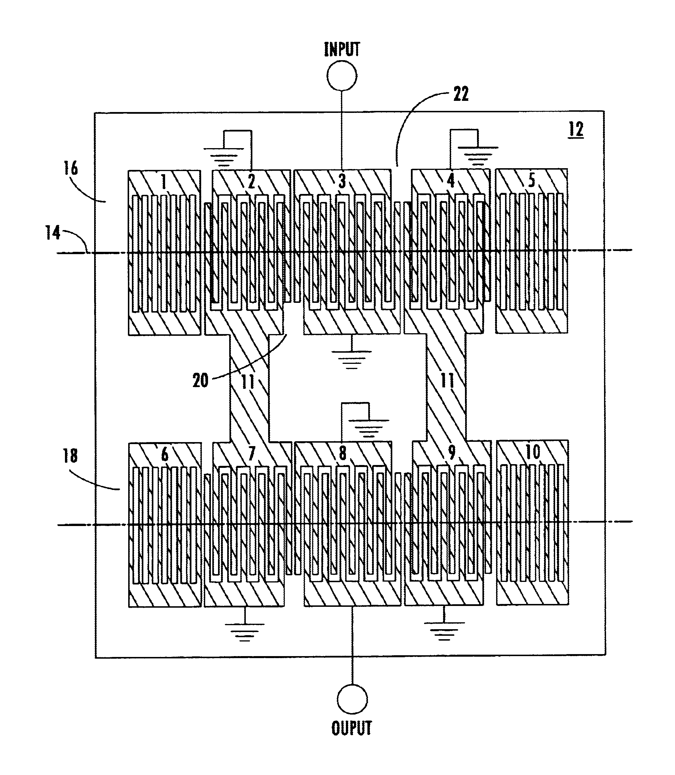
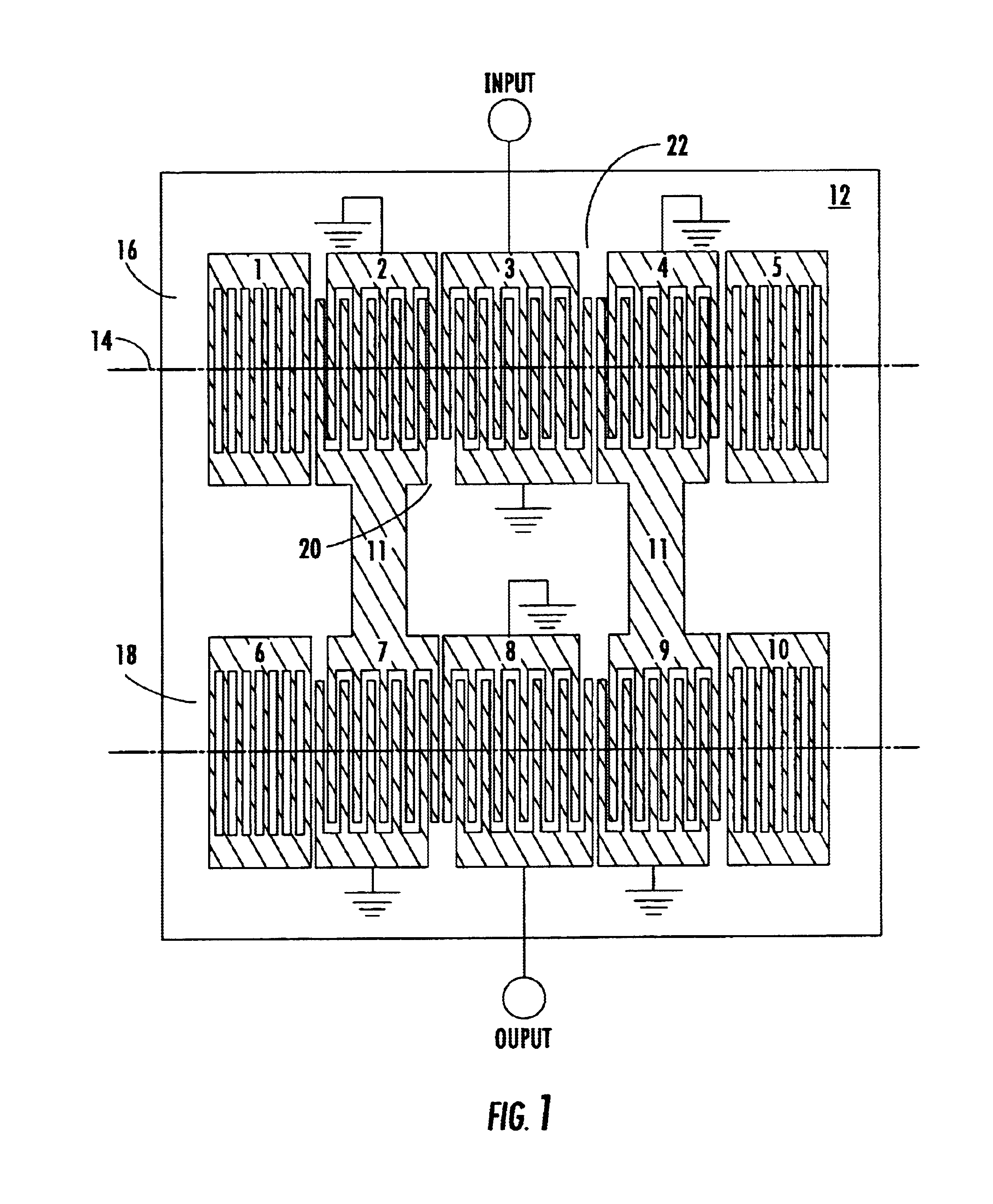
FIG. 1 is a schematic diagram of one preferred embodiment of the present invention. By way of example, a device of the present invention includes two separate LSAW resonator tracks 16, 18, connected in series. One first track 16. Track 1, includes an input IDT 3, two output IDTs 2 and 4, and two reflective gratings 1 and 5. The second track 18, Track 2, includes two input IDTs 7 and 9, an output IDT 8, and two reflective gratings 6 and 10. The output IDTs 2, 4 of the first tr...


PUM


Abstract

A longitudinally coupled leaky surface acoustic wave (LSAW) resonator filter has a wide bandwidth, low insertion loss and return loss characteristics, and high power handling capability. The LSAW resonator filter includes a plurality of longitudinally coupled LSAW resonator tracks disposed upon a piezoelectric substrate and connected in series. The resonator tracks each include reflective gratings and interdigital transducers (IDTs) disposed end-to-end. Acoustic resonant cavities are formed between each IDT and its neighboring IDTs or gratings by chirping the fingers of the IDT in the vicinity of the cavities. Phase discontinuity is eliminated; reflective bulk acoustic wave scattering is reduced; and improved insertion loss and power handling capability are achieved.

Description

FIELD OF THE INVENTIONThe present invention relates to a bandpass filter using a leaky surface acoustic wave (LSAW) resonator employing a plurality of longitudinally coupled LSAW resonators which are connected in series, and more particularly, to a longitudinally coupled LSAW resonator with improved performance due to thicker or denser metalization than previously feasible.BACKGROUND OF THE INVENTIONAs the telecommunications industry and society continue to push for mobile communications devices which are smaller, lighter, less expensive, and more energy efficient, the requirements for bandpass filters within these devices become increasingly stringent. Where once transversely coupled surface acoustic wave (SAW) resonator filters were widely used, high-performance transversal SAW filters or longitudinally coupled SAW or LSAW filters have begun to take their place. Transversal SAW filters have the advantages of high flexibility, wide bandwidth, and flat group delay time. However, wit...

Claims


Application Information

Patent Timeline
Patent Type & Authority Patents(United States)
IPC IPC(8): H03H9/145H03H9/00H03H9/64H03H9/25
CPCH03H9/14555H03H9/6489H03H9/6469
Inventor ABBOTT, BENJAMIN P.CARON, JOSHUA J.CHEEMA, KAMRAN S.
Owner TRIQUINT
Why Eureka
Try Eureka