Lawn mower guide and discharge

a mower and guide technology, applied in the field of mowers, can solve the problem of not being able to accumulate grass clippings and allowing continuous grass cutting operations

Inactive Publication Date: 2005-03-08
HONDA MOTOR CO LTD
View PDF16 Cites 57 Cited by
  • Summary
  • Abstract
  • Description
  • Claims
  • Application Information

AI Technical Summary

Benefits of technology

Specifically, in the present invention, the guide is placed along the scroll portion for allowing grass clippings to swirl within the bagging-mode housing while directing them toward the grass discharge passage, the guide being provided beneath the top plate of the housing, and the rear guide end of the guide is opposed to the passage opening facing the housing of the grass discharge passage, so that the direction of an air flow swirling grass clippings within the housing, that is, a swirling flow can be gradually changed and guided toward the passage opening with the guide.
In the present invention, as described above, the rear guide end of the guide has a wave shape. Thus air flows at depressions in the wave shape interfere with air flows at projections to reduce the generation of vortex flows, resulting in a straightened air flow flowing into the passage opening. As a result, in the bagging mode or the intermediate mode, grass clippings easily flow into the passage opening. Grass clippings are thus allowed to smoothly flow into the grass receptacle through the grass discharge passage to be more securely received.

Problems solved by technology

No accumulation of grass clippings allows continuous grass cutting operations.

Method used


Image

  • Lawn mower guide and discharge
  • Lawn mower guide and discharge
  • Lawn mower guide and discharge

Examples


first embodiment

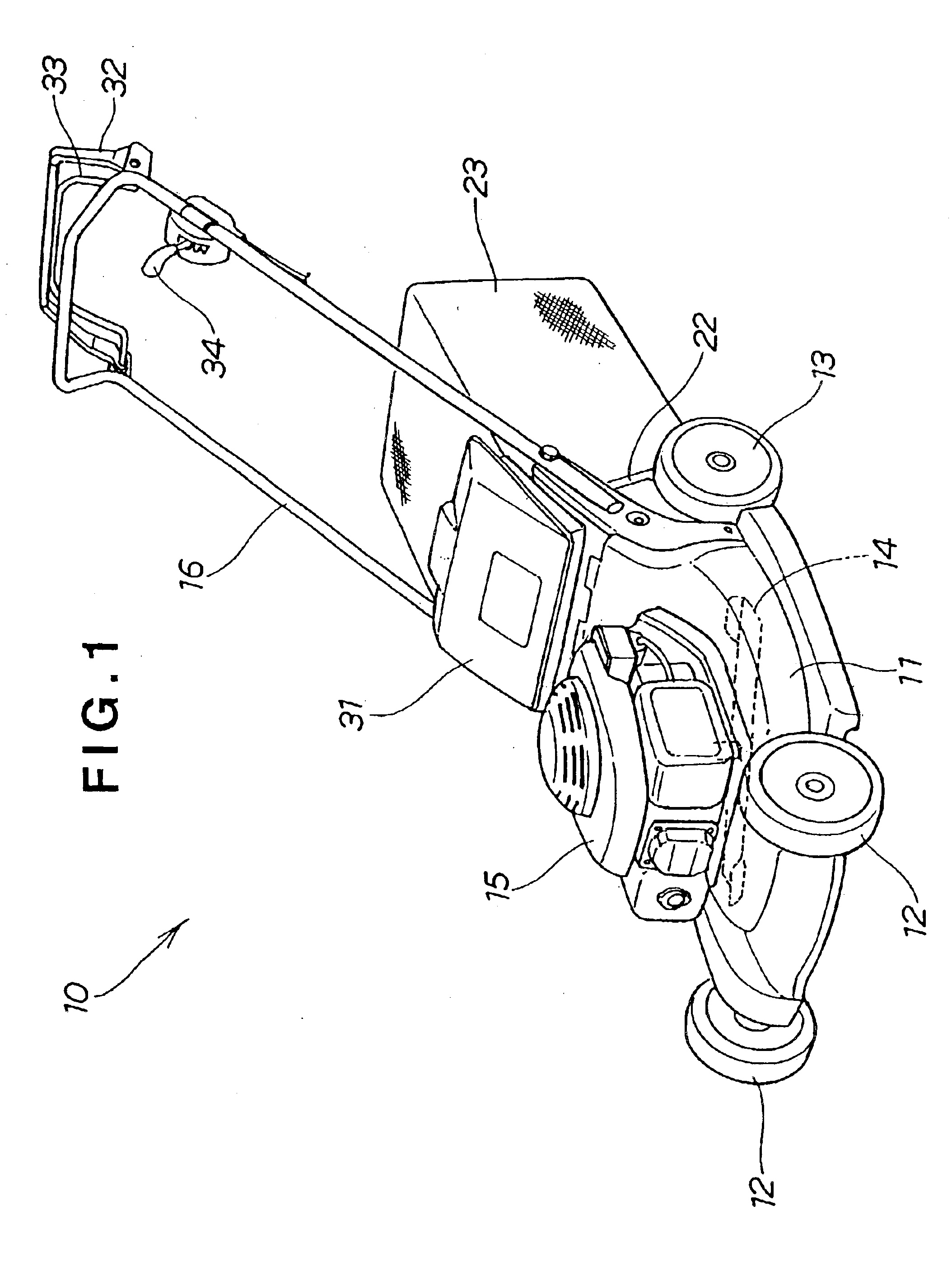
Initial reference is made to FIGS. 1 to 15 illustrating a lawn mower of the present invention.

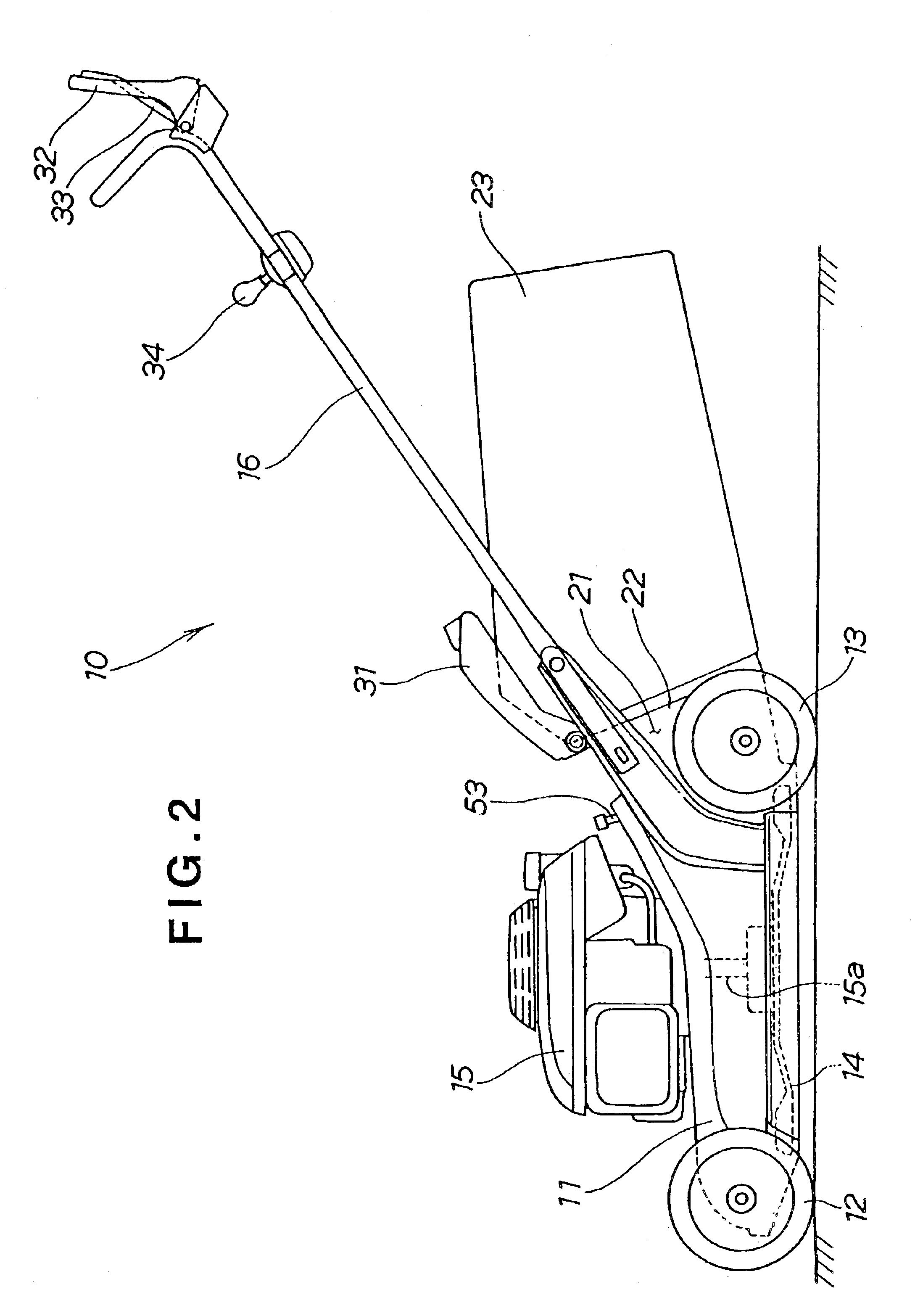
In FIG. 1, a lawn mower 10 of this embodiment has a housing 11 as a body, left and right front wheels 12, 12 provided at the front of the housing 11, and left and right rear wheels 13, 13 as driving wheels provided at the rear of the housing 11 (Only the left ones of the left and right ones are shown in the figure.). The lawn mower 10 further has a single grass cutting blade 14 provided in a central portion within the housing 11, an engine 15 provided on the top of the housing 11 for driving the rear wheels 13, 13 and the cutting blade 14, and a continuously variable transmission (not shown) interposed between the engine 15 and the rear wheels 13, 13 within the rear of the housing 11. An operating handle 16 extends rearward from the housing 11. The lawn mower 10 is a walk-behind self-propelled working machine.

As shown in FIG. 2, an output shaft 15a extends downward from the engine 15 as a p...

second embodiment

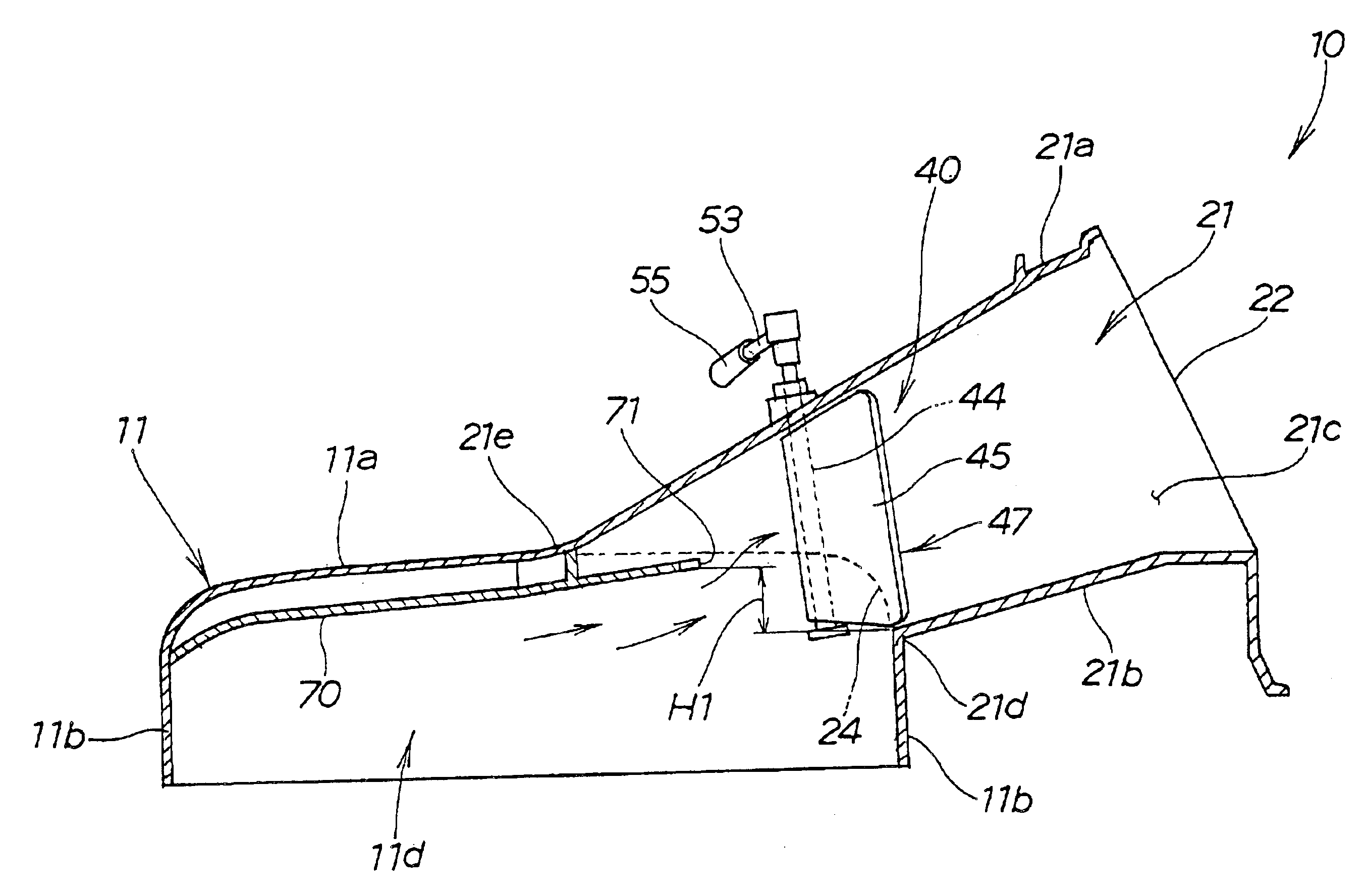
As shown in FIGS. 16, 17 and 18, a lawn mower 100 modified is characterized in that an openable and closable lid 101 is provided at an outlet of a grass discharge passage 21, a member for opening and blocking the grass discharge passage 21 is a plug member 180 (plug) to be removed out of or inserted into the grass discharge passage 21, and a guide 170 is provided at a scroll portion 11d.

The lawn mower 100 of the second embodiment has, as shown in FIG. 18, in order to efficiently perform bagging-mode operations, the scroll portion 11d provided to the housing 11 for allowing grass clippings to swirl within the housing 11 while directing them to the grass discharge passage 21, and has, in order to efficiently perform mulching-mode operations, the guide 170 placed along the scroll portion 11d, being provided beneath a top plate 11a of the housing 11, and a rear guide end 171 of the guide 170 opposed to a passage opening 24. The configurations of the components will be described in det...


PUM


Abstract

A lawn mower has a power source for rotationally driving an output shaft. A housing has an interior space having a generally spiral-shaped portion. A cutting blade is disposed in the interior space of the housing and is connected to the output shaft for rotation therewith to cut grass while the spiral-shaped portion of the interior space generates a swirling airflow allowing the cut grass to swirl within the interior space. An enclosure is connected to the housing and has a grass discharge passage having an inlet opening disposed in communication with the interior space of the housing for discharging grass cut by the cutting blade and swirling within the interior space of the housing. A guiding member is disposed in the interior space of the housing for gradually changing a direction of the swirling airflow and the swirling cut grass and for guiding the swirling airflow and the swirling cut grass toward the grass discharge passage of the enclosure.

Description

BACKGROUND OF THE INVENTION1. Field of the InventionThe present invention relates to lawn mowers, and more particularly, to rotary lawn mowers for cutting grass by rotating along the grass cutting blades housed in housings opening downward.2. Background InformationConventional rotary lawn mowers include (1) lawn mowers of a type for use in a so-called bagging mode for receiving grass cut by cutting blades in grass receptacles such as bags and (2) lawn mowers of a type for use in a so-called mulching mode for cutting grass cut by cutting blades more finely within housings and discharging it downward of the housings. The lawn mowers (1) can remove all cut grass (grass clippings), providing a good finish of the cut grass, and are thus commonly used in golf courses or the like. The lawn mowers (2) can eliminate the need for the work of “dumping grass clippings” by returning grass clippings to the lawns, and are thus commonly used in parks or the like.It is, however, inconvenient to sele...

Claims


Application Information

Patent Timeline
Patent Type & Authority Patents(United States)
IPC IPC(8): A01D34/63A01D42/00A01D34/71A01D34/67A01D34/81
CPCA01D34/71A01D42/005A01D2101/00
Inventor IIDA, TETSUOKOBAYASHI, TAKAOSASAKI, HIROMITSUSHIMADA, KENZOSHIN, MASANORI
Owner HONDA MOTOR CO LTD
Why Eureka
Try Eureka