

Tire/wheel assembly and run-flat support member
- Summary
- Abstract
- Description
- Claims
- Application Information
AI Technical Summary
Benefits of technology
Problems solved by technology
Method used
Image

Examples
example
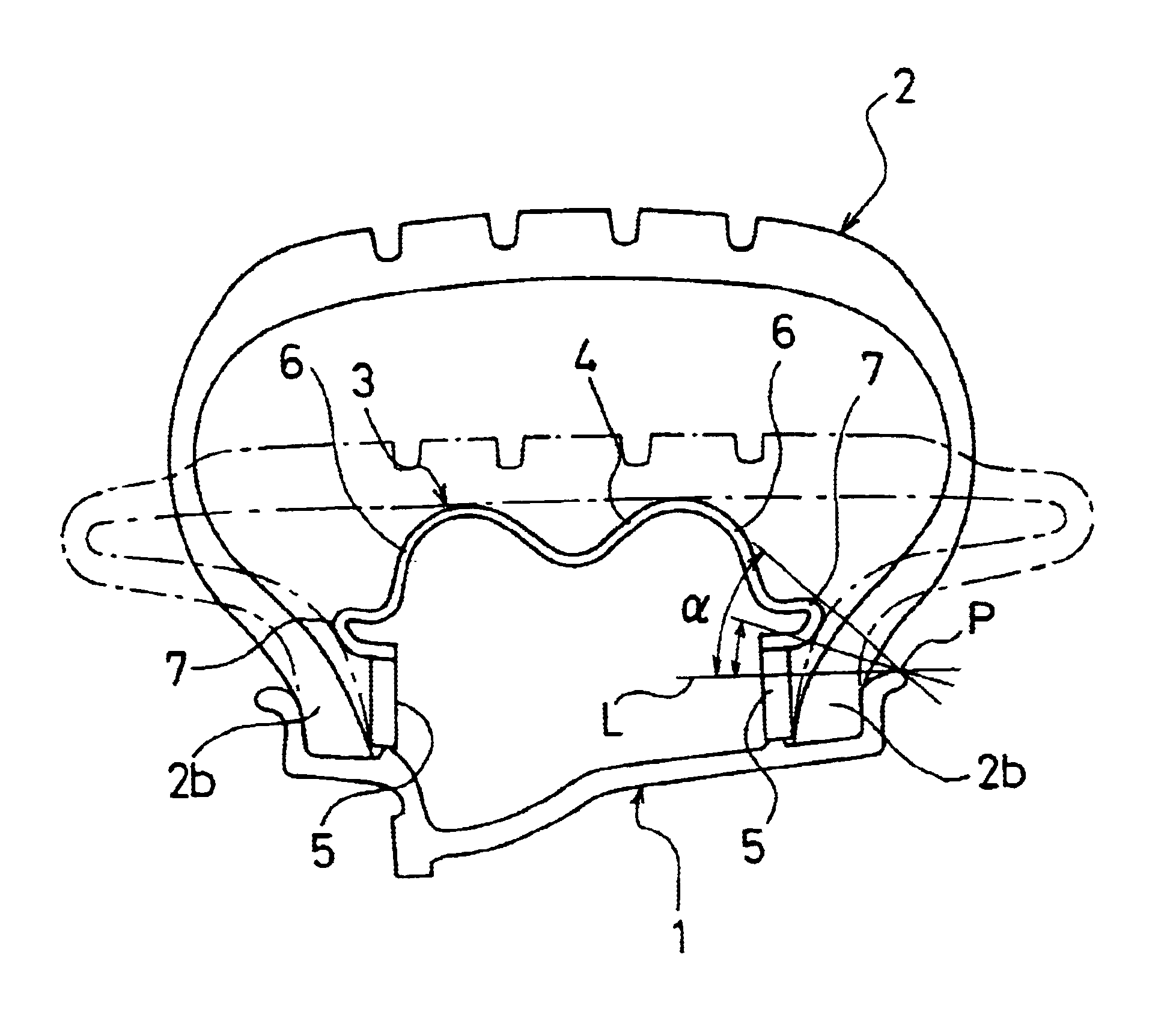
Prepared was a tire / wheel assembly (wheel) including a pneumatic tire with a tire size of 205 / 55R16 89V and a wheel having a rim size of 16×6½JJ, to which a run-flat support member according to the configuration of FIG. 1 is inserted and assembled. The run-flat support member is configured from a circular shell that is made by processing a 1.0 mm-thick steel plate and has protruding portions formed on both sides thereof, and elastic rings that are made of high hardness rubber with a thickness of 12.0 mm and are assembled to the circular shell (example).
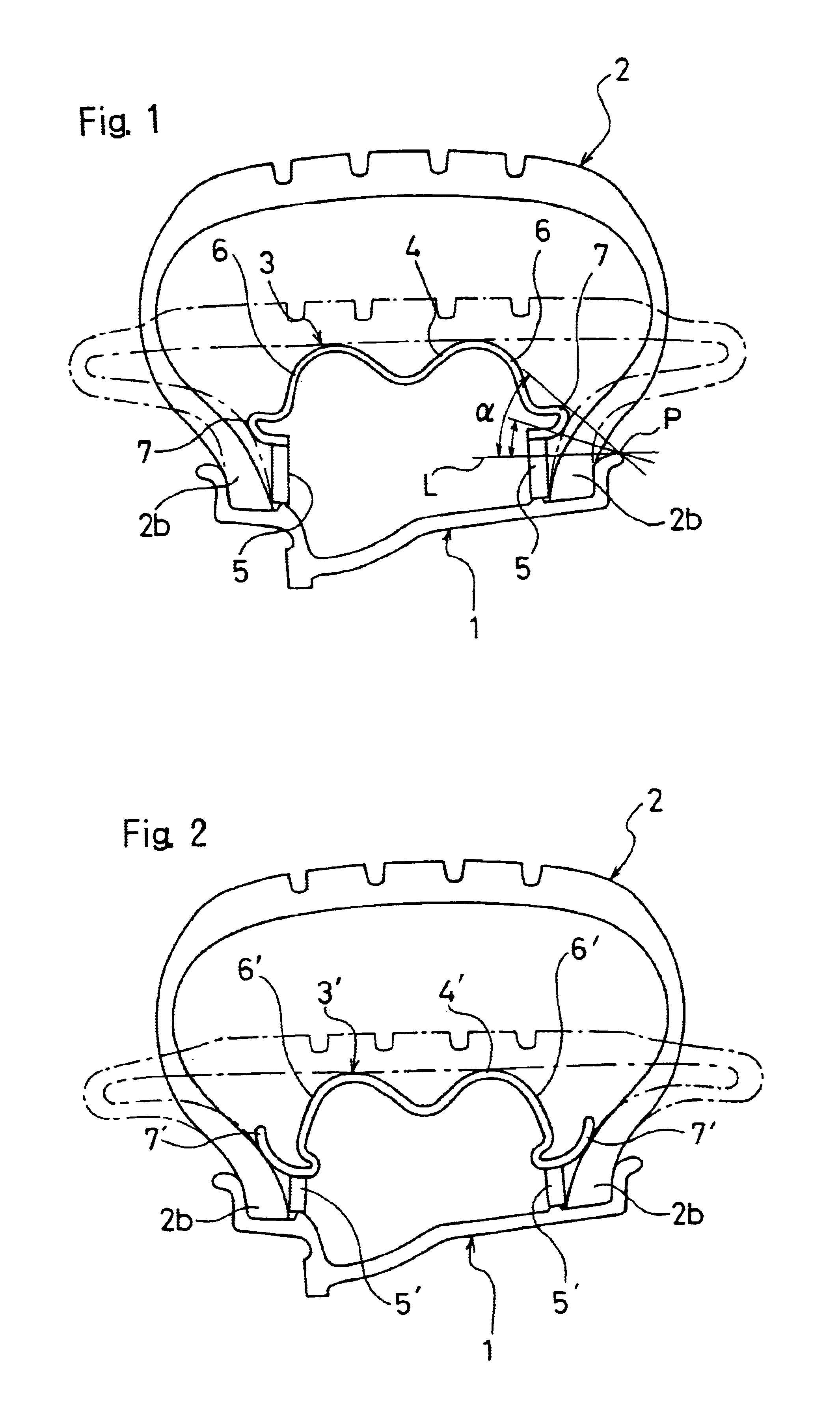
For comparison, prepared was a tire / wheel assembly (wheel) having the same configuration as that of the above-described example, except for that no protruding portions were provided in the circular shell of the run-flat support member, and that the high hardness rubber thickness of the elastic ring was changed to 15.0 mm (Conventional example).
With regard to the above two types of tire / wheel assemblies, driving stability and the weigh...
PUM
 Abstract
Description
Claims
Application Information