Chip collecting apparatus for tip dresser

a technology of tip dresser and collecting apparatus, which is applied in the direction of edge grinding machine, manufacturing tools, and electromechanical maintenance, etc., can solve the problems of low collection rate, difficult visual recognition, and worn out electrode tips used for spot welding or the like, so as to improve the accuracy of positional relationship, reduce processing steps, and easy to check

Inactive Publication Date: 2005-03-08
SUBARU CORP
View PDF14 Cites 17 Cited by
  • Summary
  • Abstract
  • Description
  • Claims
  • Application Information

AI Technical Summary

Benefits of technology

Accordingly, it is an object of the present invention to provide a chip collecting apparatus for a tip dresser capable of easily checking the positional relationship between electrode tips and a dressing body during teaching operation without detaching the whole device, significantly reducing processing steps required for teaching, and easily checking the presence or absence of faulty dressing during dressing operation from the exterior.

Problems solved by technology

Conventionally, electrode tips used for spot welding or the like are worn out (or deformed) when welding work is repeated.
However, there is a problem in that the chips tend to be released by the relative swing or rotation of the dressing body and the electrode tips during grinding work, and all the chips cannot be collected into the collection vessel, resulting in a low collection rate.
However, when the cover main body for collecting the chips generated during dressing operation is mounted on the dresser main body, as in the above prior art, it becomes difficult to visually recognize the positional relationship between the electrode tips and the dressing body; therefore, it is necessary to temporarily remove the cover main body from the dresser main body and to perform teaching, posing a problem in increasing the number of processing steps required for teaching.
Furthermore, since the dresser main body is covered by the cover main body, the dressed state of the electrode tips cannot be checked from the exterior, causing inconvenience of being unable to check faulty dressing such as insufficient dressing and excessive dressing.

Method used


Image

  • Chip collecting apparatus for tip dresser
  • Chip collecting apparatus for tip dresser
  • Chip collecting apparatus for tip dresser

Examples


third embodiment

FIG. 9 shows the invention.

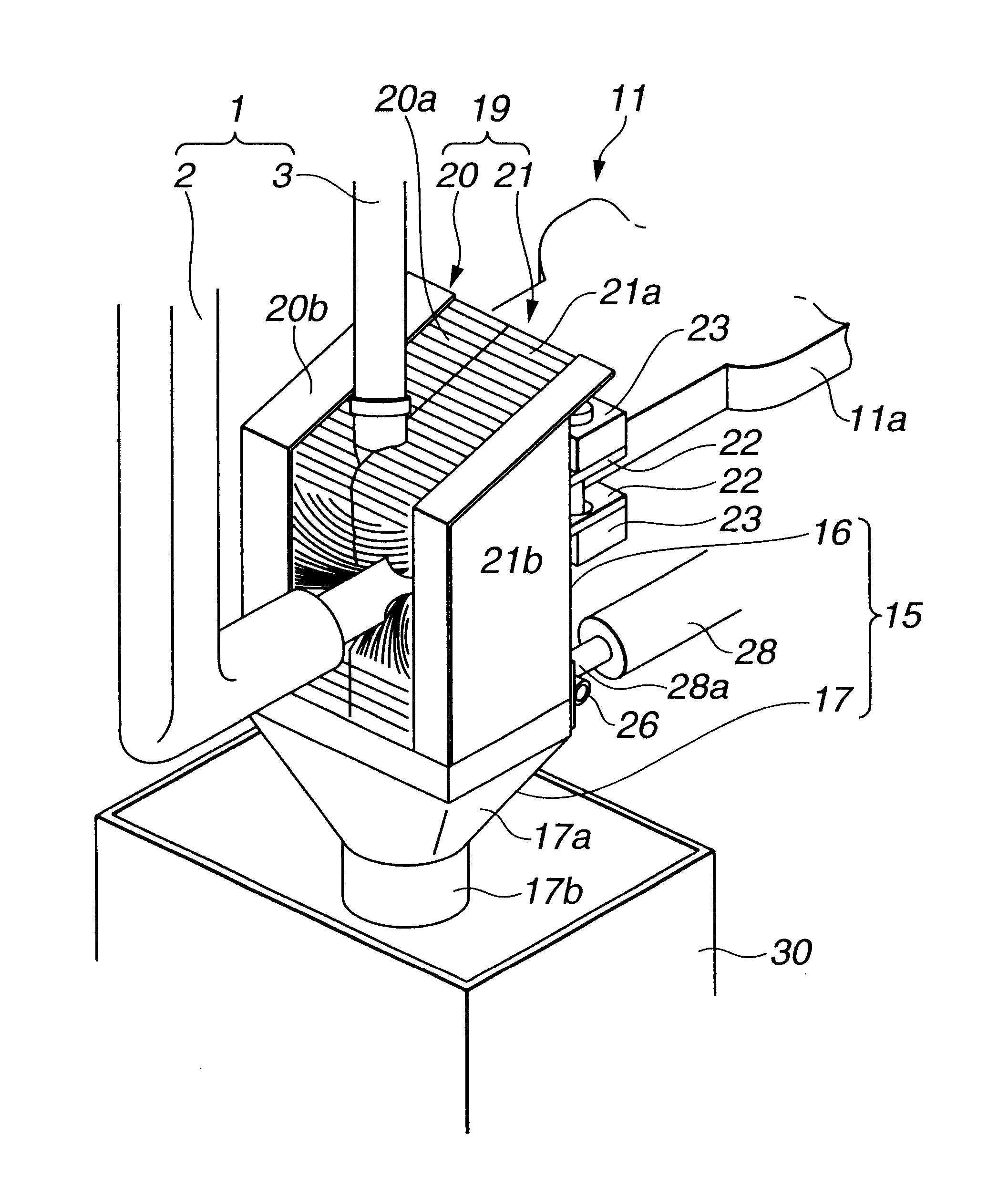
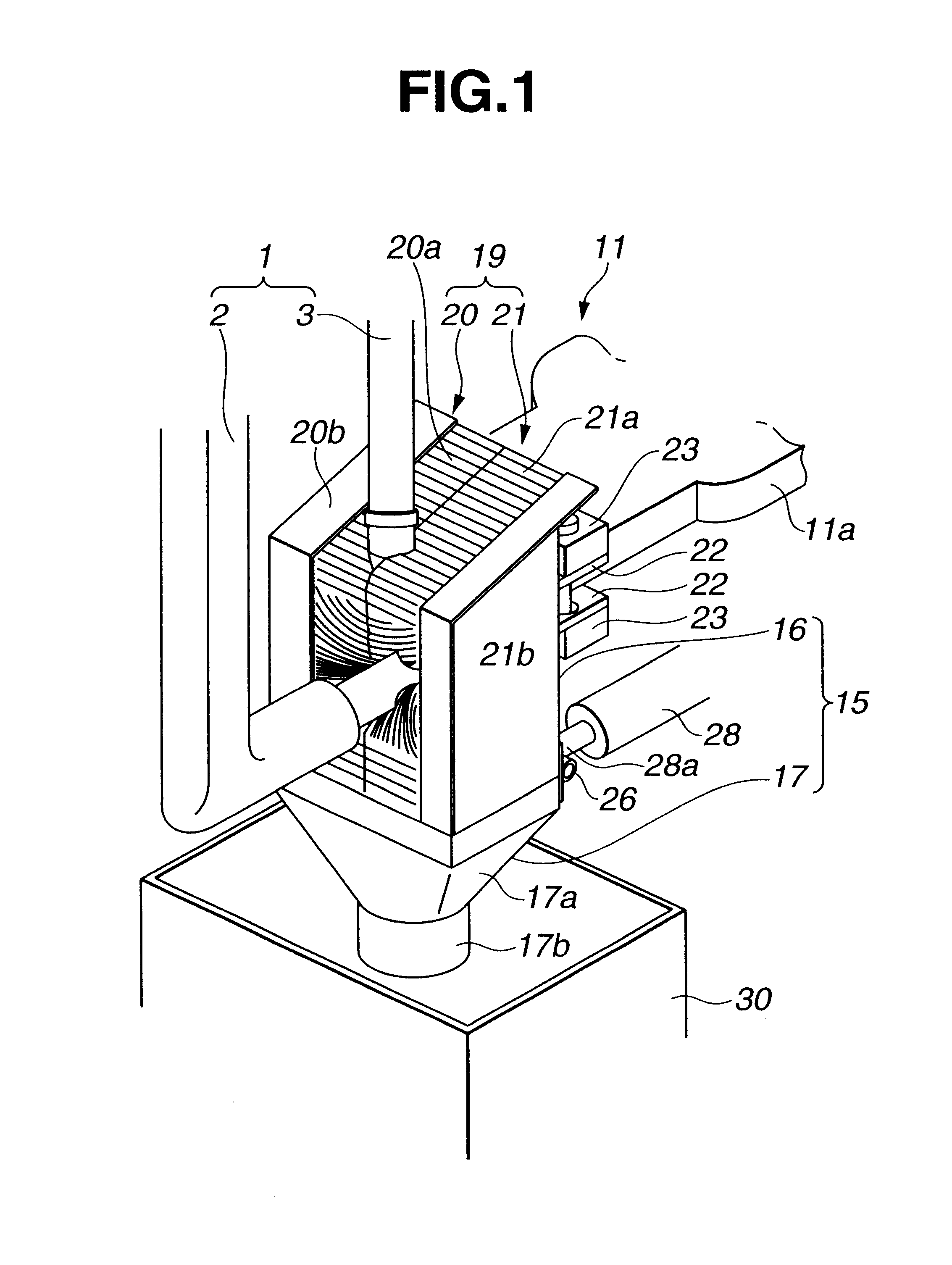
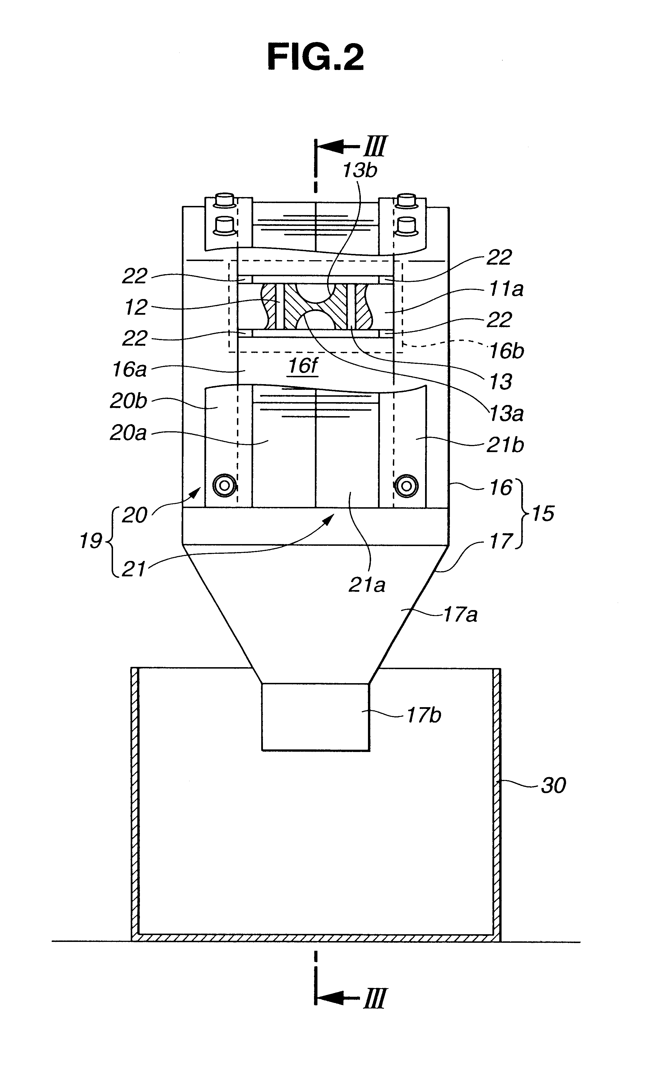
A chip pickup case 45 according to this embodiment has a window 45b opened in a side 45a thereof, through which the positional relationship between the dressing body 13 and the electrode tips 4 and 5 can be visually checked, the window 45b being blocked by a transparent plate 46 made of acryl or the like.

An arm insertion port 45c opened in the front of the chip pickup case 45 is blocked by a pair of brushes 47a and 47b constituting a shielding member 47, and un upper-arm insertion port 45d is formed in the top of the chip pickup case 45 whereas a chip guide surface 45e is formed in a tapered shape at the bottom and a chip discharge port 45f is opened at the end thereof.

According to this embodiment, since the positional relationship between the electrode tips 4 and 5 supported by the welding gun 1 and advancing into the chip pickup case 45 and the dressing body 13 can be visually recognized through the window 45b from the exterior, not only the state in whi...


PUM

PropertyMeasurementUnit
elastic deformationaaaaaaaaaa
shapeaaaaaaaaaa
widthaaaaaaaaaa

Abstract

In a chip collecting apparatus for a tip dresser of the present invention, a chip pickup case mounted on a dresser main body is divided into an upper case and a lower case, and the lower end of an arm admission port formed in the upper case is opened downward. During teaching operation, the lower case is rotated to open the lower end of the upper case, through which the insertion of a first gun arm into a lower chamber can be visually checked, and thus an electrode tip provided at the end thereof and a dressing body for dressing the end of the electrode tip are guided such that the central axes thereof conform to each other.

Description

BACKGROUND OF THE INVENTION1. Field of the InventionThe present invention relates to a chip collecting apparatus for a tip dresser for collecting chips generated when dressing electrode tips.2. Description of the Related ArtConventionally, electrode tips used for spot welding or the like are worn out (or deformed) when welding work is repeated. When welding work is performed with a worn-out electrode tip, welding of desired quality cannot be obtained; accordingly, electrode tips are periodically dressed to maintain welding quality.For example, Japanese Unexamined Patent Application Publication No. 6-122082 discloses a tip dresser for dressing electrode tips in which after the upper and lower surfaces of a dressing body have been tightly pressed by a pair of electrode tips provided at opposed ends of a welding gun, and the welding gun is swung around the central axis of each electrode tip for grinding, thereby dressing the electrode tips.Recently, the recycle of chips is contemplated...

Claims


Application Information

Patent Timeline
Patent Type & Authority Patents(United States)
IPC IPC(8): B24B19/16B24B19/00B23K11/30B24B55/00B24B55/04B24B55/06
CPCB23K11/3063B24B19/16B24B55/06B24B55/04Y10T409/304256Y10T409/303752
Inventor SUNAGA, SHOUICHIHARUYAMA, YUICHIRO
Owner SUBARU CORP
Why Eureka
Try Eureka