Sand-belt finishing machine having lift device

Inactive Publication Date: 2005-03-08
WANG WANG TIEN
View PDF9 Cites 19 Cited by
  • Summary
  • Abstract
  • Description
  • Claims
  • Application Information

AI Technical Summary

Benefits of technology

The primary objective of the present invention is to provide a sand-belt finishing machine having a lift device

Problems solved by technology

However, the thickness of the wooden board is not a constant, so that it is necessary to adjust the posit

Method used


Image

  • Sand-belt finishing machine having lift device
  • Sand-belt finishing machine having lift device
  • Sand-belt finishing machine having lift device

Examples


Embodiment Construction

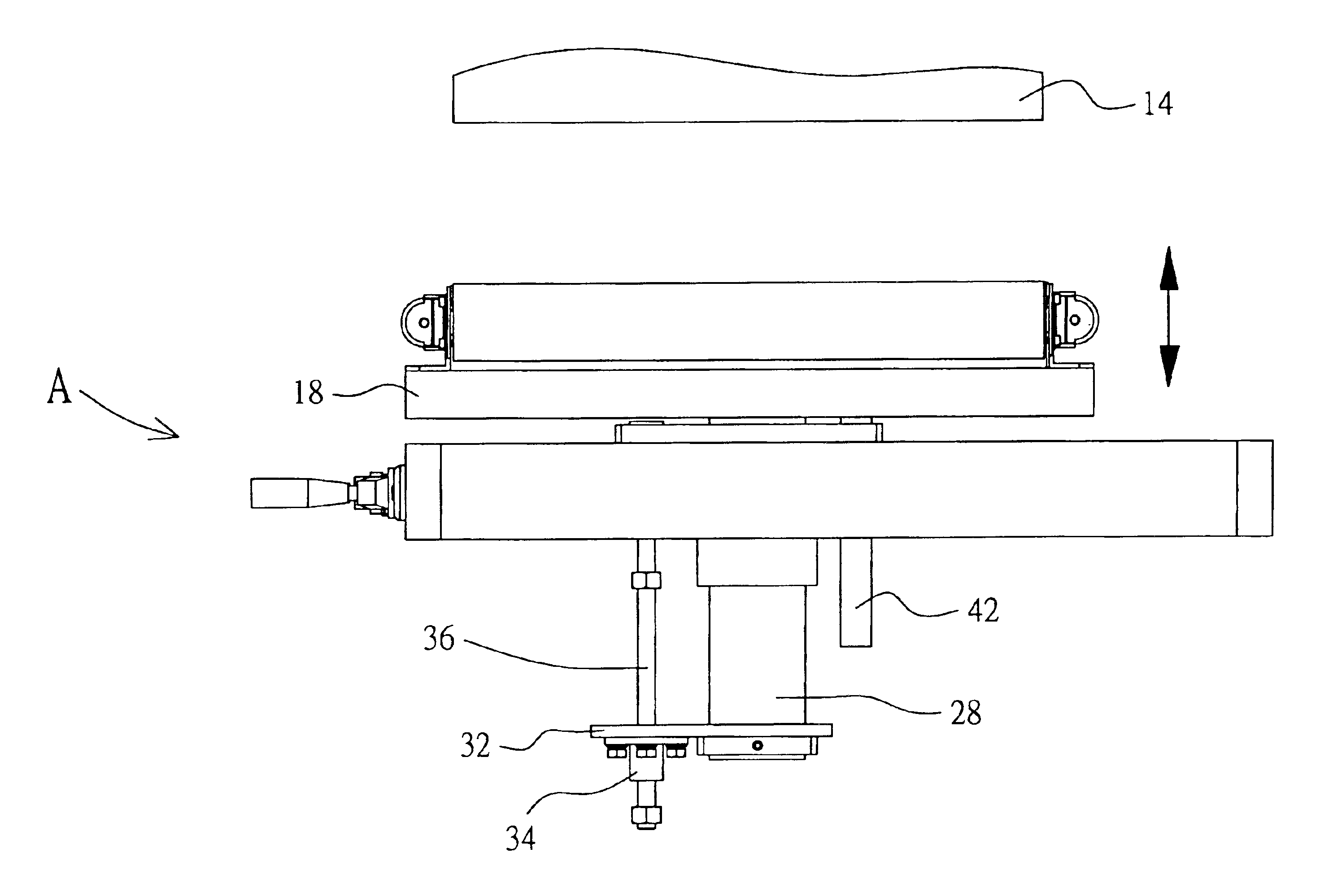
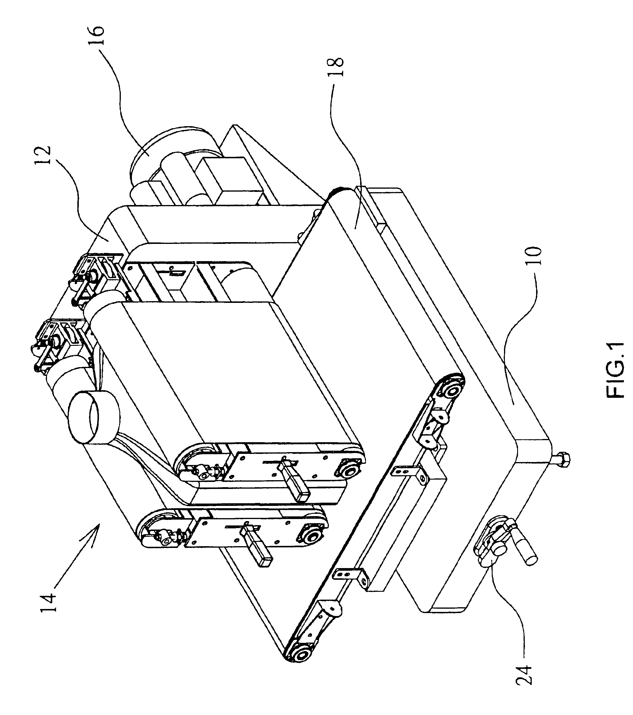
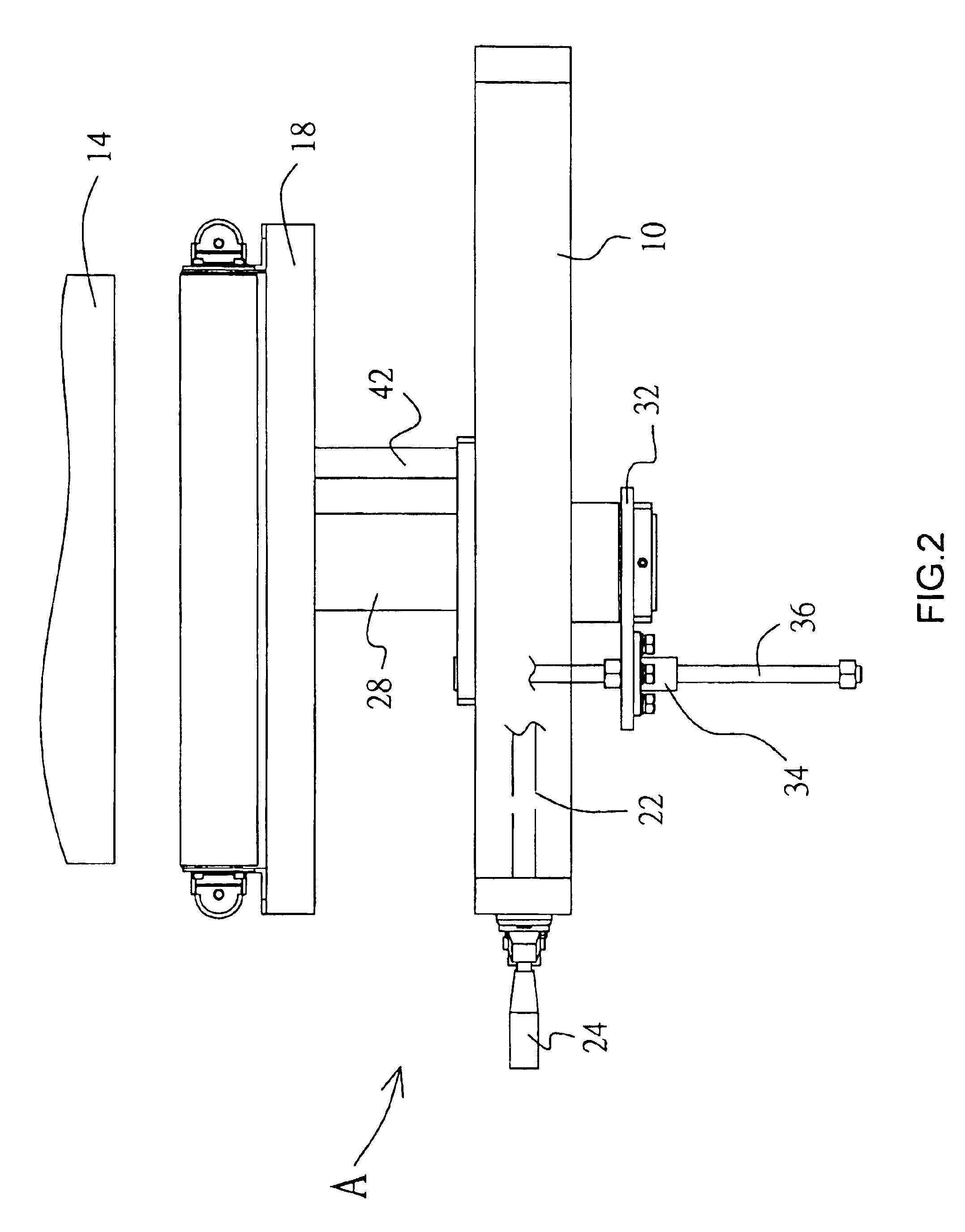
Referring to the drawings and initially to FIGS. 1-3, a sand-belt finishing machine in accordance with the preferred embodiment of the present invention comprises a main frame 10 disposed at a horizontal state, an upright seat 12 mounted on and vertical to the main frame 10, two grinding devices 14 mounted on the upright seat 12, a driving device 16 mounted on the upright seat 12 and connected to the grinding devices 14 for actuating the two grinding devices 14, a conveyor platform 18 mounted between the grinding devices 14 and the main frame 10, and a lift device “A” mounted between the conveyor platform 18 and the main frame 10 for adjusting the position of the conveyor platform 18.

The lift device “A” includes a propeller shaft 22 mounted in the main frame 10 and having a first end provided with a beveled gear 26 and a second end protruded outward from the main frame 10, and an operation handle 24 mounted on the main frame 10 and secured on the second end of the propeller shaft 22...


PUM


Abstract

A sand-belt finishing machine includes a main frame, at least one grinding device, a conveyor platform mounted between the grinding device and the main frame, and a lift device mounted between the conveyor platform and the main frame for adjusting the position of the conveyor platform. The lift device includes a propeller shaft, a shaft, a support plate, a driving rod, and a slide rod. Thus, the distance between the grinding devices and the conveyor platform can be adjusted arbitrarily by the lift device, so that the grinding devices can be used to grind workpieces of different thickness.

Description

BACKGROUND OF THE INVENTION1. Field of the InventionThe present invention relates to a sand-belt finishing machine, and more particularly to a sand-belt finishing machine having a lift device that can be operated easily and conveniently, thereby facilitating the user operating the lift device.2. Description of the Related ArtA conventional sand-belt finishing machine comprises two rollers, and a sand belt reeved around the two rollers for grinding a workpiece, such as a wooden board, placed on a conveyor platform. However, the thickness of the wooden board is not a constant, so that it is necessary to adjust the position of the conveyor platform so as to change the distance between the conveyor platform and the sand belt.SUMMARY OF THE INVENTIONThe primary objective of the present invention is to provide a sand-belt finishing machine having a lift device that can be operated rapidly, easily and conveniently, thereby facilitating the user operating the lift device.Another objective o...

Claims


Application Information

Patent Timeline
IPC IPC(8): B24B21/04B24B47/00B24B47/20B24B41/06
CPCB24B21/04B24B47/20B24B41/068
Inventor WANG, WANG TIEN
Owner WANG WANG TIEN
Why Eureka
Try Eureka