Method and apparatus for improved memory core testing

a technology of memory core and memory core, applied in the field of memory devices, can solve the problem that the test problem described above becomes more sever

Inactive Publication Date: 2005-03-08
APPLE INC
View PDF15 Cites 32 Cited by
  • Summary
  • Abstract
  • Description
  • Claims
  • Application Information

AI Technical Summary

Problems solved by technology

A problem with memory cores, whether conventional as seen in FIG. 1a, multi-port as seen in FIG. 1b, or otherwise, is the testing of such devices.
Furthermore, as a system (e.g., a computing...

Method used


Image

  • Method and apparatus for improved memory core testing
  • Method and apparatus for improved memory core testing
  • Method and apparatus for improved memory core testing

Examples


Embodiment Construction

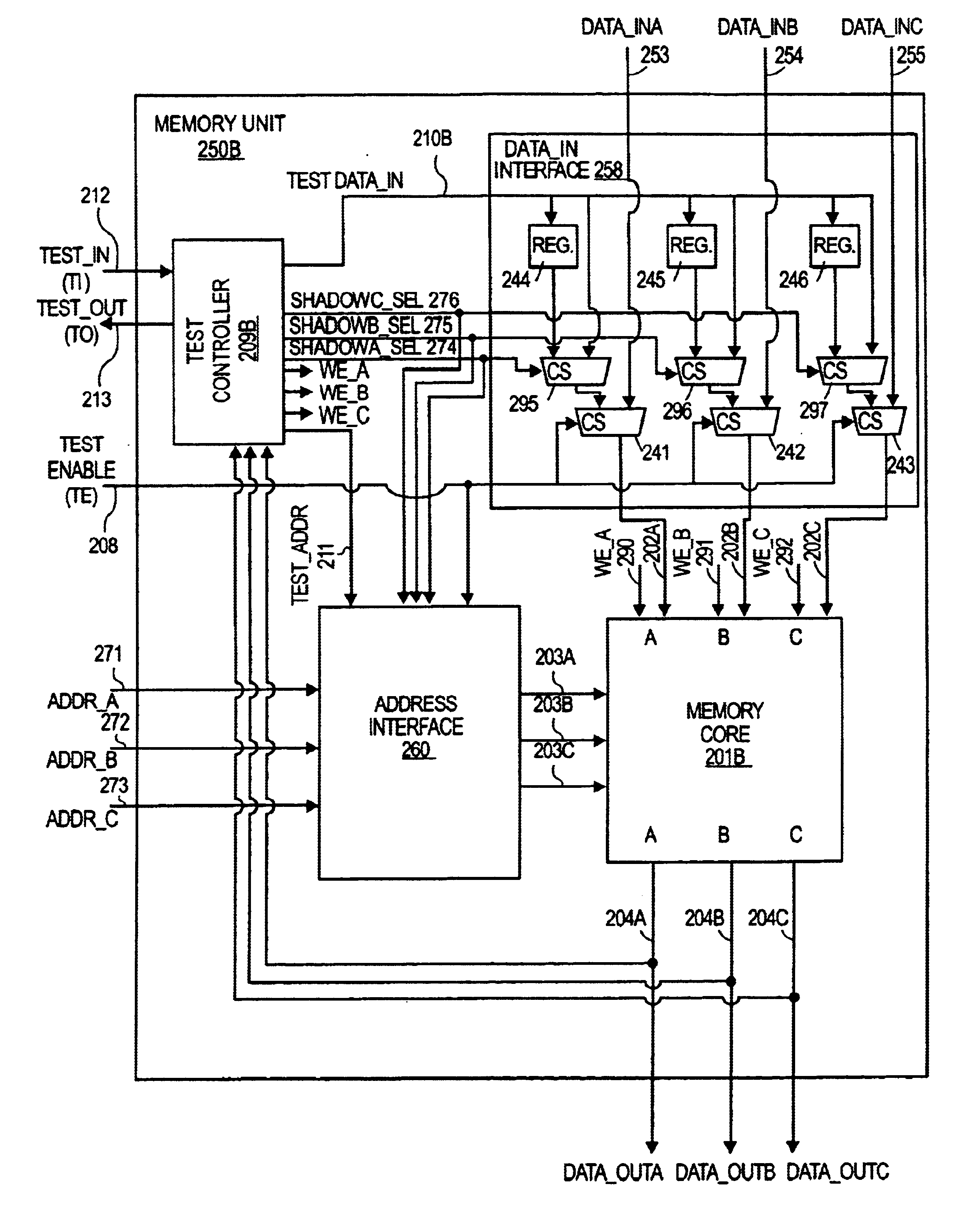
A solution to the problem described in the background includes a memory unit having a controller that is coupled to a memory core. FIG. 2a shows such an approach. A memory unit 250a is a memory core 201a supported by testing circuitry that is local to the memory core. By incorporating a memory unit into a design, a design simultaneously provides a mechanism for storing data (i.e., the memory core 201) and a mechanism for testing the memory core 201 (e.g., the test controller 209a and its associated logic).

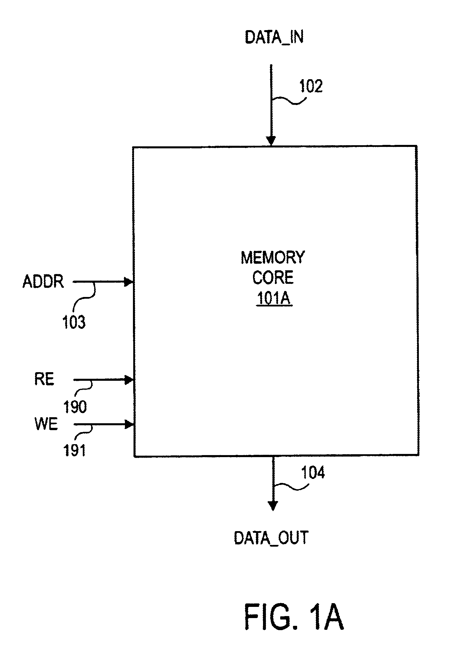
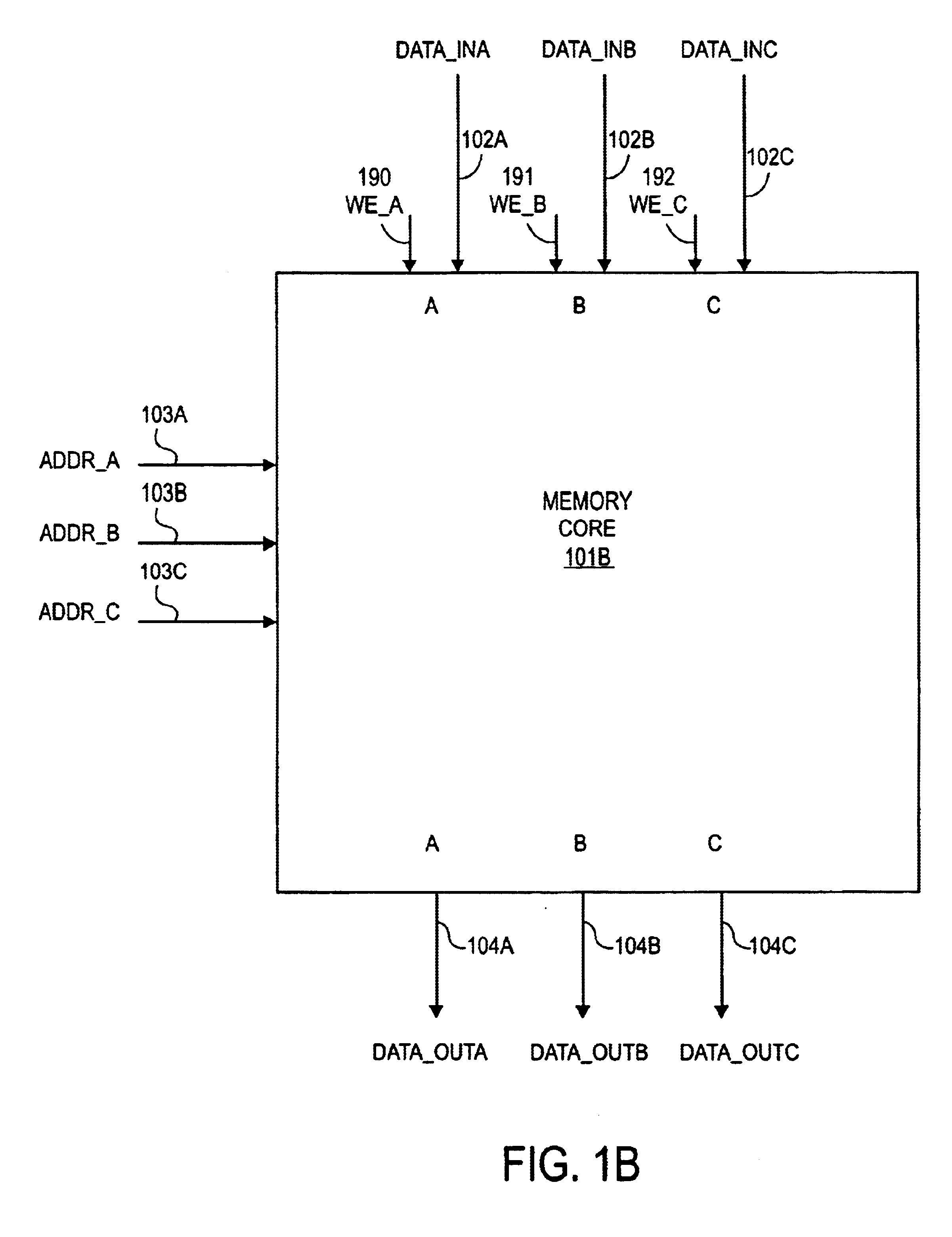
The memory core 201a of FIG. 2a corresponds to the conventional memory core 101a of FIG. 1a. However, as explained in more detail below, the approach of FIG. 2a is extendable to other memory core designs such as the multi-port memory core 101b shown in FIG. 1b. An example of such an approach is seen in FIG. 2b and discussed in more detail further below. Note that the memory unit 250a of FIG. 2a shows a controller 209a coupled to a memory core 201a.

The controller 209a corresponds t...


PUM


Abstract

A memory unit is described that has a controller coupled to a memory core through an interface circuit. The interface circuit has a test data input that receives test data from the controller. The interface circuit also has a system data input that receives data from a system. The interface circuit has a data output that is coupled to a data input of the memory core.

Description

FIELD OF THE INVENTIONThe field of invention relates generally to memory devices; and more specifically, to a method and apparatus for improved memory testing.BACKGROUNDa. Conventional Memory CoreFIG. 1a shows a memory core 101a. Typically, a memory core 101a is constructed with Dynamic Random Access Memory (DRAM) or Static Random Access Memory (SRAM) cells that store binary information (i.e., a “1” or “0”). For RAM cells, binary information is written to the cells via the Data_In input 102 and Information is read from the cells via the Data_Out output 104.Other forms of cells that may be used to construct memory core 101a include Content Addressable Memory (CAM) cells and Read Only Memory (ROM) cells. CAM cells are designed to look for a “match” between stored information and offered information. As such, offered information is presented at the Data_in input 102 and the address location of matching data is presented at the Data_Out output 104. ROM cells are typically programmable. ...

Claims


Application Information

Patent Timeline
IPC IPC(8): G11C29/00G11C29/14G11C29/48
CPCG11C29/48G11C29/14G11C29/1201G11C8/16
Inventor YOUNGS, LYNN R.IWAMOTO, DEREK F.
Owner APPLE INC
Why Eureka
Try Eureka