Tool holder and cord locking means

a tool holder and locking means technology, applied in the field of tool holders, can solve the problems of cumbersome and/or dangerous for the operator to carry individual service tools, affecting the safety of operators, and reducing the recoil of manual starters

Inactive Publication Date: 2005-03-15
OBERNDORFER MICHAEL J
View PDF12 Cites 11 Cited by
  • Summary
  • Abstract
  • Description
  • Claims
  • Application Information

AI Technical Summary

Benefits of technology

In accordance with one embodiment, the tool holder is permanently attached to a retractable pull cord incorporated into a manual starter of a power-operated device. The service tool or tools are pivotally mounted on the tool holder, allowing the service tool or tools to be folded out for servicing a power operated device and subsequently folded in and stowed compactly within the main body of the tool holder. An additional aspect of the present embodiment is a mechanism integrated into the tool holder for reducing the recoil of a manual starter.
According to further embodiments of the present invention, a cord locking means is described for securing the retractable pull cord of the manual starter in an extended state. The cord locking means affords a range of mobility to the tool holder, permitting the tool holder and service tools thereon to be easily used to service a power-operated device, while at the same time remaining tethered to the power operated devices by the retractable pull cord.

Problems solved by technology

Power operated devices often require maintenance that necessitates the use of service tools.
The operator of a powered device may carry individual service tools, but depending on their shape and size it may be cumbersome and / or dangerous for the operator to carry the individual service tools while using the power-operated device.
Pichler et al. contend that, as an essential operating component of the power operated device, a removable tool carrier fashioned as described above makes misplacing the tool carrier practically impossible.
However, the '835 patent does not successfully solve the problem associated with a service tool's vulnerability to being misplaced.
For instance, it is not unforeseeable that under certain circumstances, once removed for the purpose of servicing a power operated device, the tool carrier of the '835 patent may be misplaced, forgotten, or dropped in an area from which it may not be easily retrieved.
Further, due to the functional relation of the tool carrier of the '835 patent to the power-operated device, misplacement of this tool carrier would create an additional undesirable consequence of rendering the power-operated device inoperable.

Method used


Image

  • Tool holder and cord locking means
  • Tool holder and cord locking means
  • Tool holder and cord locking means

Examples


Embodiment Construction

The forthcoming description sets forth various embodiments envisioned for practicing the present invention. This description is not to be taken in a limiting sense, but is made for the purpose of illustrating the general tenants of the invention. To ascertain the scope of the invention, one should reference the issued claims.

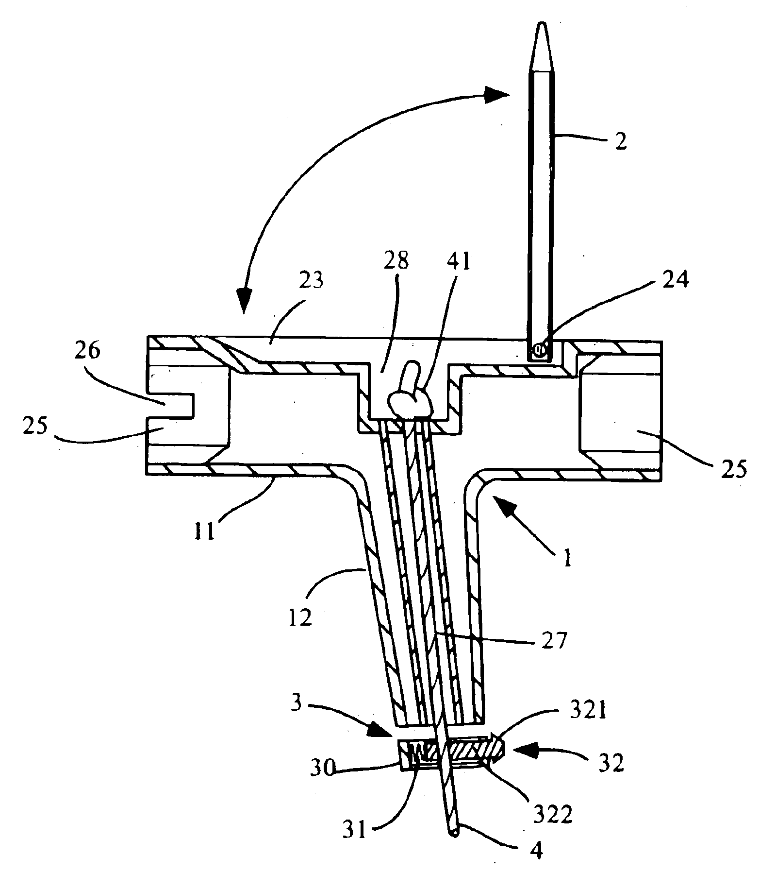
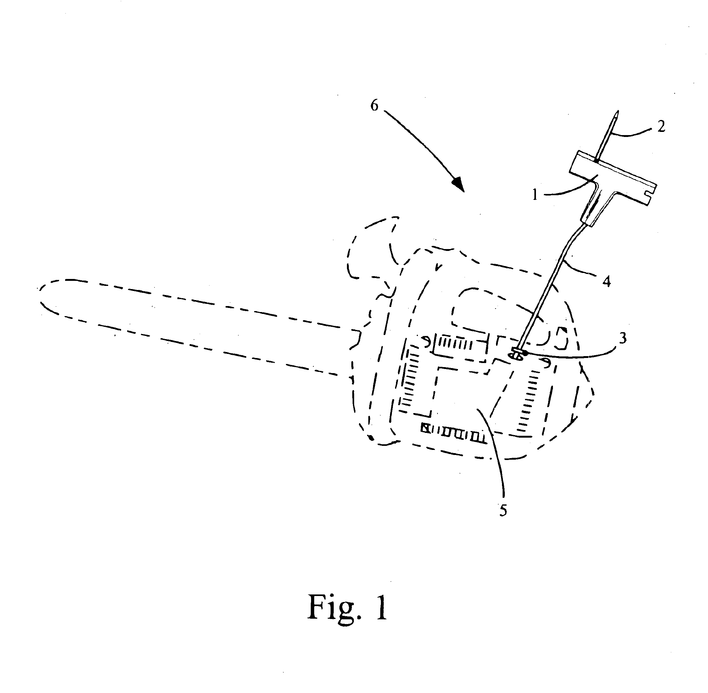
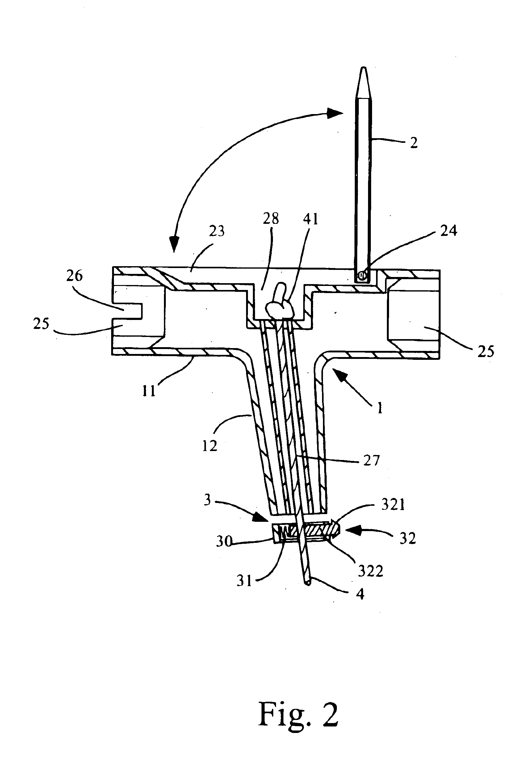
The present invention remedies the problems associated with the prior art by incorporating a service tool or tools into a standard operating component of a power-operated device, and further by selecting a component that is permanently coupled to the power-operated device. Subsequently, a further aspect of the invention provides mobility for the fixed component to which the service tool or tools are integrated. Providing mobility for the fixed component allows practical use of the service tool or tools while preserving their permanence to the power operated device, virtually eliminating any of the service tool's vulnerability to being misplaced.

Looking now to th...


PUM


Abstract

A tool holder containing at least one service tool for servicing a power-operated device. The tool holder is permanently attached to a retractable pull cord incorporated into a manual starter of a power-operated device. The service tool or tools are pivotally mounted on the tool holder, allowing the service tool or tools to be folded out for servicing the power operated device and subsequently folded in and stowed compactly within the main body of the tool holder. The tool holder may include a mechanism for reducing the recoil of the manual starter. A cord locking means secures the retractable pull cord of the manual starter in a retracted state. The cord locking means affords a range of mobility to the tool holder, permitting the tool holder and service tools thereon to be easily used to service a power-operated device.

Description

BACKGROUND OF THE INVENTION1. Field of the InventionThe present invention relates generally to a tool holder. More specifically the present invention relates to a pull handle of a power operated device incorporating a tool holder having at least one service tool permanently attached. The pull handle is permanently coupled to the pull cord. Also described is a means for locking the pull cord in a retracted state.2. Discussion of the Related ArtPower operated devices often require maintenance that necessitates the use of service tools. This maintenance can include cleaning, tightening, and sharpening components of the device, or removing and attaching parts and accessories of the device. To this end, there exists a plethora of service tools and several ways of holding service tools so that they are readily available once such servicing is required. The operator of a powered device may carry individual service tools, but depending on their shape and size it may be cumbersome and / or dan...

Claims


Application Information

Patent Timeline
Patent Type & Authority Patents(United States)
IPC IPC(8): B25B13/06B25B13/00B25B23/00B25F1/00B25F1/04B23D71/04
CPCB23D71/04B25F1/04B25B23/00B25B13/06
Inventor OBERNDORFER, MICHAEL J.
Owner OBERNDORFER MICHAEL J
Why Eureka
Try Eureka