Rapid clutch device for straightening shearing machine for wire

A technology of clutch device and shearing machine, which is applied in the direction of non-mechanical drive clutches, clutches, magnetic drive clutches, etc., can solve the problems of high production cost, jamming, and many times of shearing, and achieve fast moving separation speed and positioning lock The effect of staying steady and separating quickly

Inactive Publication Date: 2009-05-06
龙乐武
View PDF0 Cites 18 Cited by
  • Summary
  • Abstract
  • Description
  • Claims
  • Application Information

AI Technical Summary

Problems solved by technology

[0002] The outstanding problem of the clutch device of the existing wire rod straightening and shearing machine is: the separation of the clutch moving according to the shaped gear is to rely on the S-curve 360-degree concave groove on the outer circle of the saw-shaped gear and the electromagnet to control the deflection of the lever. In the actual use process, due to the fast rotation speed, large inertia, and many times of shearing of the clutch movable gear and the large shearing gear, it is easy to cause the protruding square iron on the clutch movable gear and the control The 7-shaped positioning hook on the partial iron plate slips, the control fails, and the processing is difficult and the production cost is high
[0007] 1. The clutch shaft cooperates with the mobile clutch saw gear and the movement of the center hole. Only two flat keys are used, and the convex and concave matching moving contacts. Each flat key only uses two 6mm countersunk screws to fix the flat key on the clutch shaft. In the keyway on the upper part, the actual steel shear force comes from the edges of the two flat keys on the clutch shaft. Due to the movement of the core hole in the groove of the clutch saw-shaped gear, there is a certain free space and clearance with the clutch protruding shaft. The shearing gear has a large shearing force and a large number of shearing times, the clutch speed of the moving clutch gear is fast, and the hook positioning recoil inertia force is large. After the machine is used for a period of time, for example, about 3-6 months, the clutch shaft will appear. The edge of the flat key and the edge of the hole groove of the supporting mobile gear are damaged, the screw of the flat key is loose, the keyway of the shaft and the flat key are seriously deformed, resulting in the incomplete engagement of the mobile clutch saw gear and the fixed clutch saw tooth on the double spur gear. If it is stuck, the machine makes a rattling sound, which seriously damages the saw-shaped teeth of the clutches on both sides, causing the machine to not work normally and causing great trouble to the user.
[0008] 2. The separation of the clutch and moving gears is accomplished by the S-curve 360-degree concave groove on the outer circle of the saw gear and the electromagnet controlling the shaft pin roller on the partial iron plate of the lever, and the movement of the saw teeth drives the clutch. The positioning stop of the 360-degree rotation of the shaft is also completed by the lever iron plate, the 7-shaped hook and the square rail protruding beside the groove of the moving saw gear. It is installed on the casing with a long screw, and there is a gap between the center sleeve of the partial iron core of the lever and the screw rod. Due to the positioning 7-shaped hook on the partial iron plate and the rolling wheel of the moving shaft pin, it is in contact with the middle center of the partial iron plate. There is a certain distance between the core and the fixed sleeve. In actual use, due to the fast rotation speed, large inertia and large shearing times of the clutch movable gear and the large shearing gear, it is easy to cause the protruding square iron on the clutch movable gear and The 7-shaped positioning hook on the control partial iron plate slips, the control fails, and continuous shearing often occurs, causing the protruding positioning square gear on the movable gear to wear into a semicircle. The 7-shaped hook on the control partial iron plate is determined by The original 90 degrees changed to 110 degrees, which caused the clutch to fail. Especially when cutting short-sized wire rod steel bars, the impact inertia force was greater, and short steel bars of about 30 cm were often cut. Often useless, in the long-term use process, the amount of scrap is astonishing, because every continuous cutting will make the clutch mobile gear groove and the control shaft pin roller contact with the 7-shaped positioning hook on the lever partial iron plate to produce impact and touch Wear and tear, the service life is greatly reduced. Under normal circumstances, the user needs to repair and replace once in about a year, which brings a lot of trouble and economic loss to the user.
[0009] 3. The clutch moves the saw gear, and the clutch control rotates 360 degrees, cutting, positioning, and stopping. The shaft pin rolling wheel; and the 7-shaped hook device to complete, but the structural processing of this 360-degree curved groove requires high precision, and it must be processed and manufactured by a special machine in multiple times before it can be completed. The processing of the clutch It brings great inconvenience, and at the same time causes the production cost to remain high

Method used


Image

  • Rapid clutch device for straightening shearing machine for wire
  • Rapid clutch device for straightening shearing machine for wire
  • Rapid clutch device for straightening shearing machine for wire

Examples


Embodiment 1

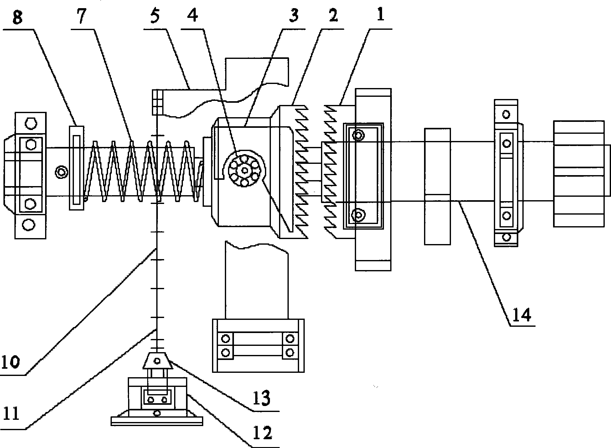
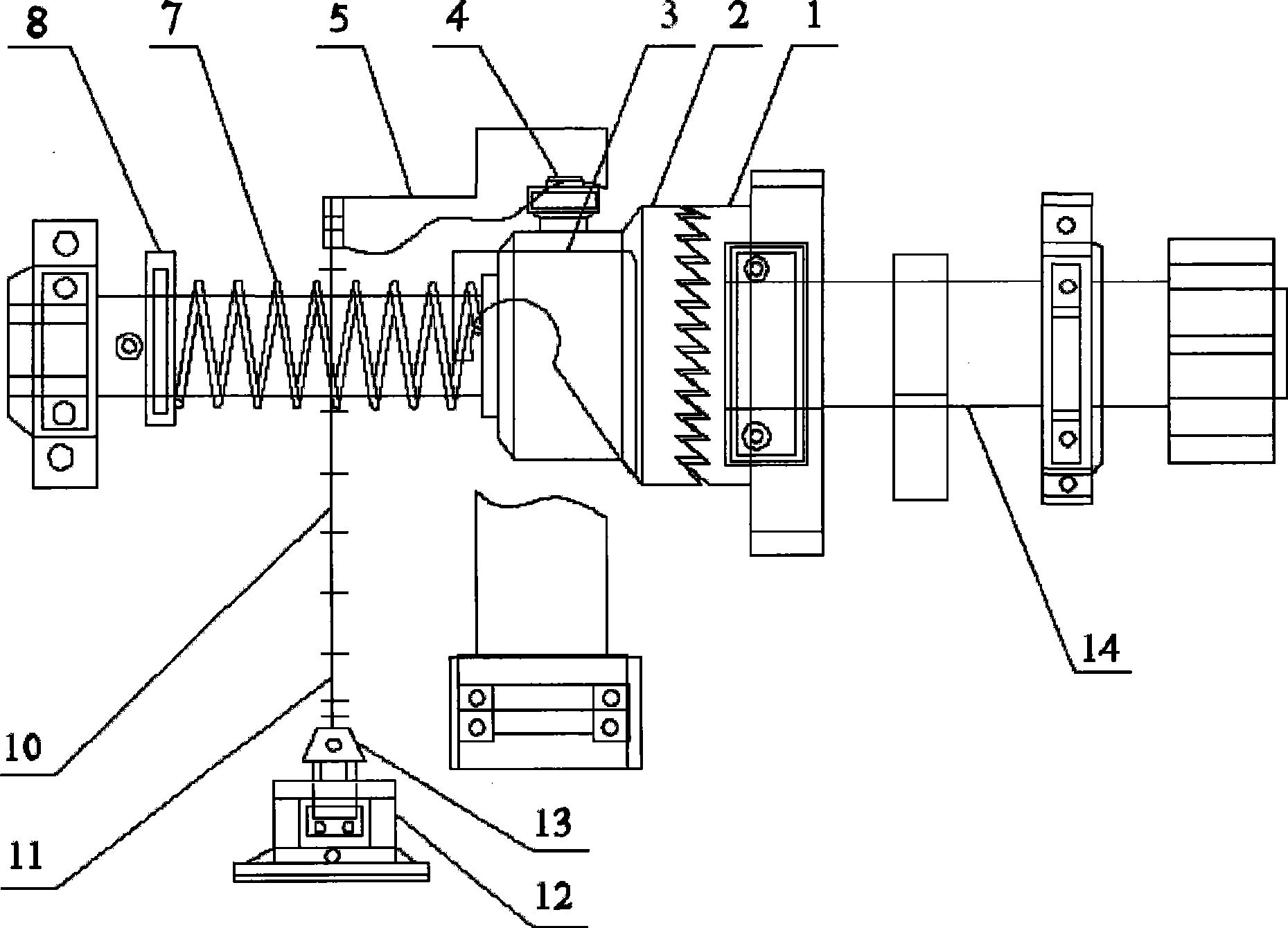
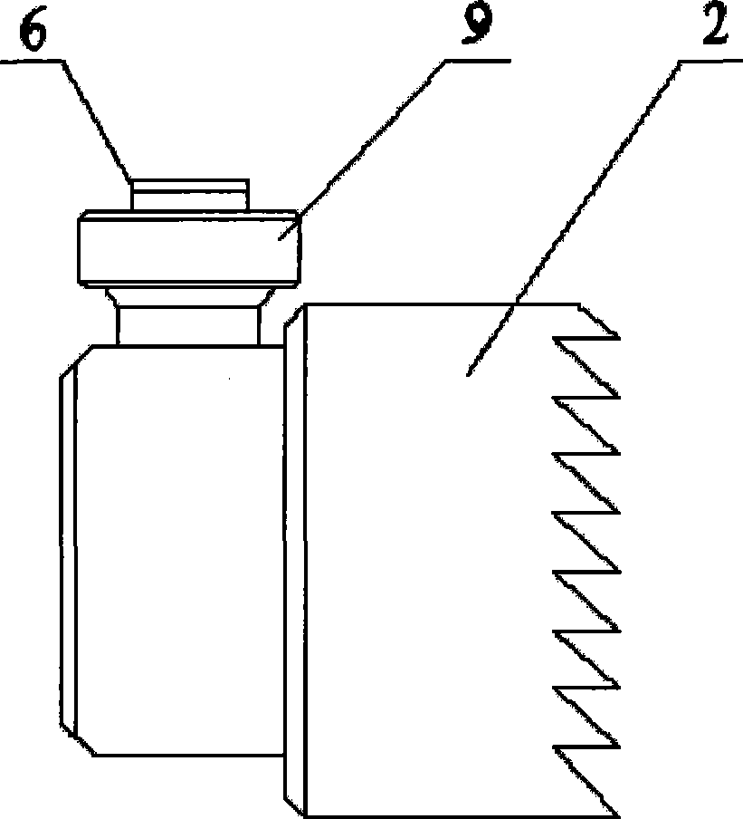
[0035] Embodiment 1. A quick clutch device for wire straightening and shearing machines, including a fixed saw gear 1, a moving saw gear 2, a tiger mouth hook 3, a return device 4, an angle iron cover plate 5, a spring 7, and a baffle 8. Actuating connectors, electromagnet frame 12, and fixed shaft 14, wherein: the fixed saw gear 1 is connected with the front end bearing of the fixed shaft 14; the moving saw gear 2 is slidingly socketed with the middle end of the fixed shaft 14; the baffle plate 8 is fixedly installed On the rear end of the fixed shaft 14; the two ends of the spring 7 are respectively fixed on the baffle plate 8 and the mobile saw gear 2; the outer circle of the mobile saw gear 2 is fixed with a return device 4; On the return device 4; the tiger mouth hook 3 is installed on the angle iron cover plate 5, and one end of the angle iron cover plate 5 is fixed on the frame; the electromagnet installed on the electromagnet frame 12 passes through the connecting piece...

Embodiment 2

[0036] Embodiment 2, a quick clutch device for a straightening and shearing machine for wire rods, wherein: the pulling connector is a chain 10, a sprocket 11, and a core hammer 13; Iron connection, center hammer 13 other ends pull angle iron cover plate 5 by sprocket wheel 11, chain 10. All the other are with embodiment 1.

Embodiment 3

[0037] Embodiment 3, a quick clutch device for a wire straightening and shearing machine, wherein: the tiger mouth hook 3 is provided with a semicircular opening, and a slope with a certain angle is provided at the lower end of the semicircular opening, and the slope and the semicircular opening smoothly transition. All the other are with embodiment 1 or 2.


PUM


Abstract

The invention relates to a rapid clutching device for wire straightening shearing machines, which comprises a fixed saw-shaped gear, a movable saw-shaped gear, a hanger which has a shape like the part of the hand between the thumb and the index finger, a returning device, an angle-iron cover plate, a movable shaft, a spring, a baffle, a sleeve shaft, a pulling connecting piece, an electromagnet frame, a fixed shaft, wherein the fixed saw-shaped gear is fixedly connected with the fixed shaft; the movable saw-shaped gear is fixedly connected with the movable shaft; the movable shaft is arranged in the sleeve shaft and is movably connected with the sleeve shaft; and the fixed saw-shaped gear movably meshes with the movable saw-shaped gear. The device has the advantages of high separation speed, small recoil force, stable positioning and locking and especially long life span, and can not be subjected to clutching failure caused by that too strong impact inertia force causes the returning device to skid and be unhooked.

Description

technical field [0001] The invention relates to a fast clutch device for automatically controlling cutting and cutting of a wire straightening machine. Background technique [0002] The outstanding problem of the clutch device of the existing wire rod straightening and shearing machine is: the separation of the clutch moving according to the shaped gear is to rely on the S-curve 360-degree concave groove on the outer circle of the saw-shaped gear and the electromagnet to control the deflection of the lever. In the actual use process, due to the fast rotation speed, large inertia, and many times of shearing of the clutch movable gear and the large shearing gear, it is easy to cause the protruding square iron on the clutch movable gear and the control The 7-shaped positioning hook on the partial iron plate slips, the control fails, and the processing is difficult, and the production cost is high. [0003] The rest of the relevant information is as follows: [0004] The clutc...

Claims


Application Information

Patent Timeline
Patent Type & Authority Applications(China)
IPC IPC(8): F16D27/10B21F1/02B21F11/00
Inventor 龙乐武龙琦
Owner 龙乐武
Why Eureka
Try Eureka