

Apparatus and method for lubricating feed mechanism of forming machine
a technology of forming machine and feed mechanism, which is applied in the direction of presses, manufacturing tools, gearing, etc., can solve the problems of difficult maintenance of lubricant film at the contact surface between the balls and the screw, uneven lubrication conditions at the respective portions of the ball screw, and difficulty in maintaining lubricant film, so as to prevent contamination of the forming machine, reduce maintenance costs, and prolong the service life of the respective portion
- Summary
- Abstract
- Description
- Claims
- Application Information
AI Technical Summary
Benefits of technology
Problems solved by technology
Method used
Image

Examples
first embodiment
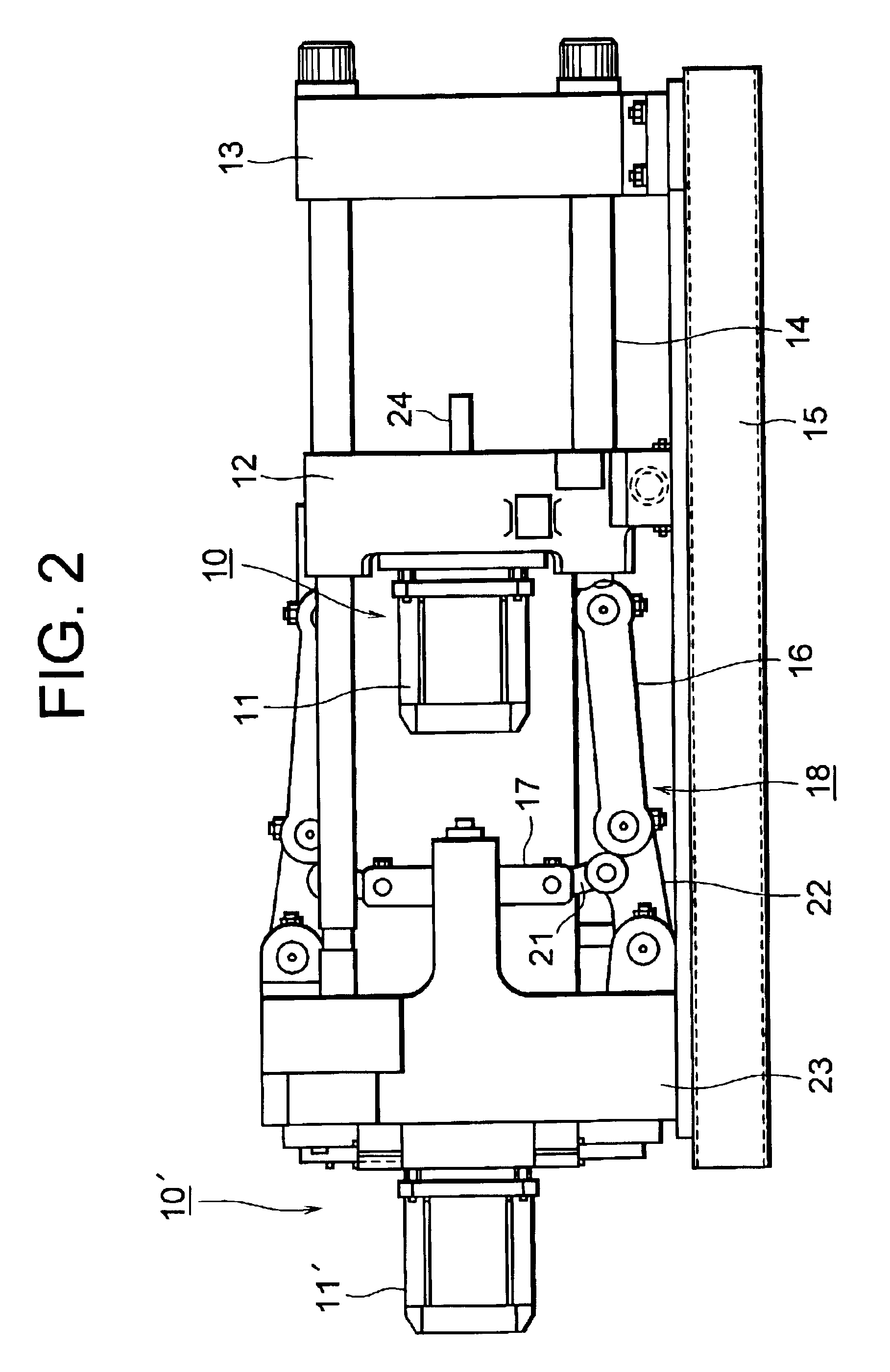
FIG. 2 is a schematic view of a mold clamping apparatus of an injection molding machine according to the present invention.
In FIG. 2, reference numeral 15 denotes a frame; 13 denotes a stationary platen, which is fixed to the frame 15; 23 denotes a toggle support, serving as a base plate, which is movably disposed on the frame 15 and is separated a predetermined distance from the stationary platen 13; 14 denotes tie bars which are disposed to extend between the stationary platen 13 and the toggle support 23; and 12 denotes a movable platen which is disposed to face the stationary platen 13 and is reciprocatable (can be moved leftward and rightward in FIG. 2) along the tie bars 14. An unillustrated stationary mold is attached to a surface of the stationary platen 13, which surface faces the movable platen 12. An unillustrated movable mold is attached to a surface of the movable platen 12, which surface faces the stationary platen 13.
A dive unit 10 is attached to the rear end (left-ha...
third embodiment
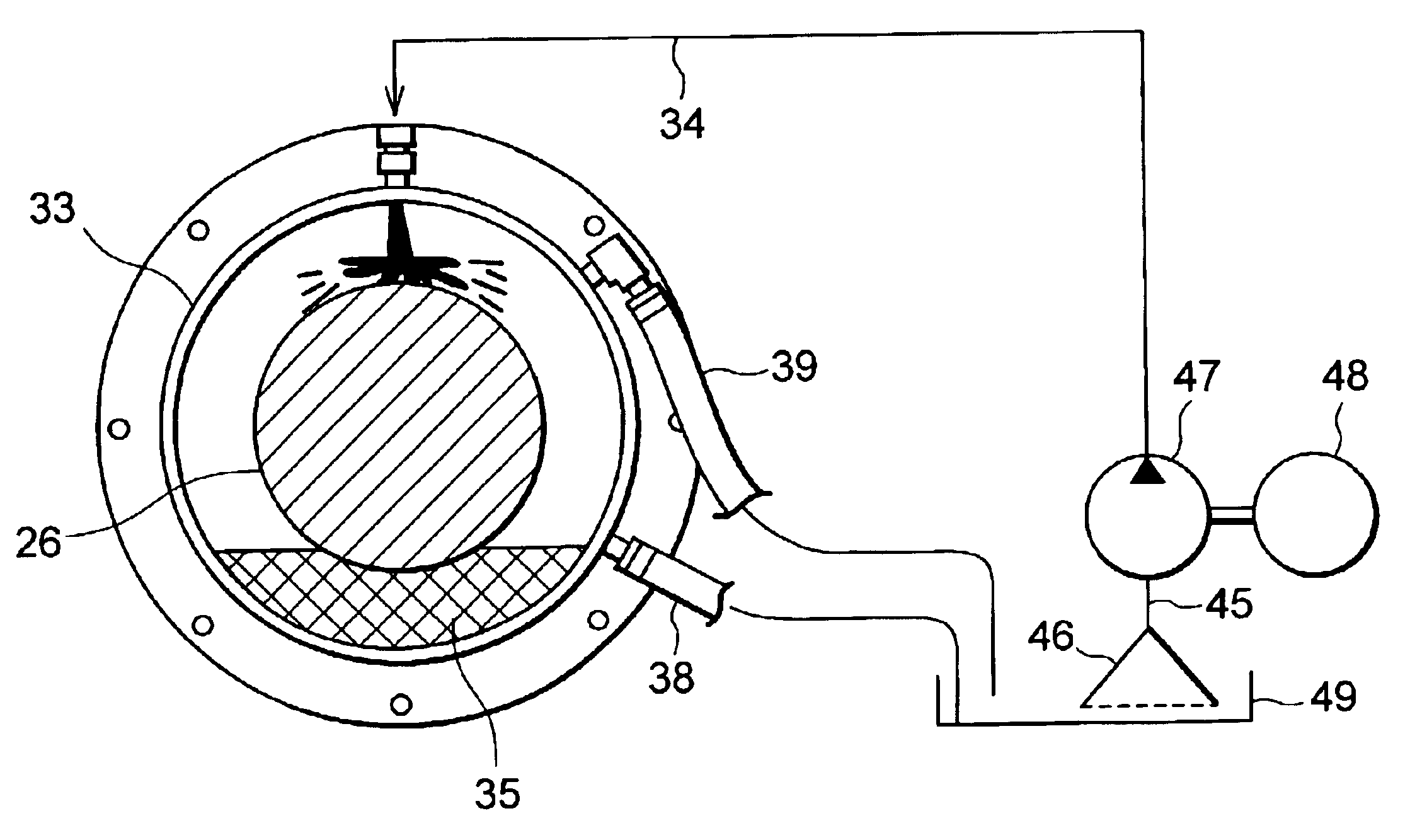
FIG. 14 is a diagram showing the configuration of the iron-content measurement unit used in the present invention.
In FIG. 14, reference numeral 74 denotes a first excitation coil, which is disposed in such a manner that the lubrication oil supply pipe 34 passes through the center thereof. Reference numeral 75 denotes a second excitation coil, which is disposed to face the first excitation coil 74. However, the lubrication oil supply pipe 34 does not pass through the center of the second excitation coil 75. A detection coil 77 is disposed at the midpoint between the first excitation coil 74 and the second excitation coil 75. The first excitation coil 74 and the second excitation coil 75 have the same configuration and are excited by the same current output from an oscillation circuit 76. Therefore, the first excitation coil 74 and the second excitation coil 75 generate magnetic fields of the same intensity in the same direction.
Therefore, at the midpoint between the first excitation ...
PUM
| Property | Measurement | Unit |
|---|---|---|
| power | aaaaa | aaaaa |
| pressure | aaaaa | aaaaa |
| rotation | aaaaa | aaaaa |
Abstract
Description
Claims
Application Information