Device for indicating the locking state of a fifth wheel coupling and sensor arrangement

a technology for indicating the locking state of a fifth wheel and sensor arrangement, which is applied in the direction of brake action initiation, vehicle, braking system, etc., can solve the problems of increasing the wear and damage of the locking latch, and increasing the risk of false detection, so as to achieve less mechanical loading

Inactive Publication Date: 2005-03-15
JOST WERKE
View PDF9 Cites 27 Cited by
  • Summary
  • Abstract
  • Description
  • Claims
  • Application Information

AI Technical Summary

Benefits of technology

Preferably, the magnet is mounted on the coupling-side end of the operating lever, particularly preferably on the coupling-side end of the handle lever. This arrangement makes it possible to mount the second sensor in a protected location within the fifth wheel. Mounting the sensor to the above-described embodiment of a one-handed actuation of the fifth wheel furthermore has the advantage that the second sensor simultaneously detects the lever mechanism and thus also the pivoted lever, such that any defect in the area of the pivoted lever is also detected.
Advantageously, the second sensor is fixed in relation to the coupling plate. As a result, the sensor itself, its connecting cables and soldered connections are less subject to mechanical loading.

Problems solved by technology

If the kingpin is driven in too high, it rises above the locking latch, which increases the risk of false detections.
In practice, however, such a positioning of the first sensor has proven to be a drawback because the locking latch must first be locked before the sensor can detect the position of the king pin in relation to the locking latch.
An incorrect positioning of the kingpin led to increased wear and damage to the locking latch and the first sensor mounted thereon, since the locking latch, even during travel, is subject to substantial impact loading, which is also transmitted to the first sensor.
Another weak point is the flexibly installed cables.
The essential drawback of the sensor arrangement of this second sensor is that there are frequent false alarms because the major part of the fifth wheel is made of steel, and actuating the operating lever changes the position of a plurality of other components in relation to the second sensor, which then trigger a false signal.

Method used


Image

  • Device for indicating the locking state of a fifth wheel coupling and sensor arrangement
  • Device for indicating the locking state of a fifth wheel coupling and sensor arrangement
  • Device for indicating the locking state of a fifth wheel coupling and sensor arrangement

Examples


Embodiment Construction

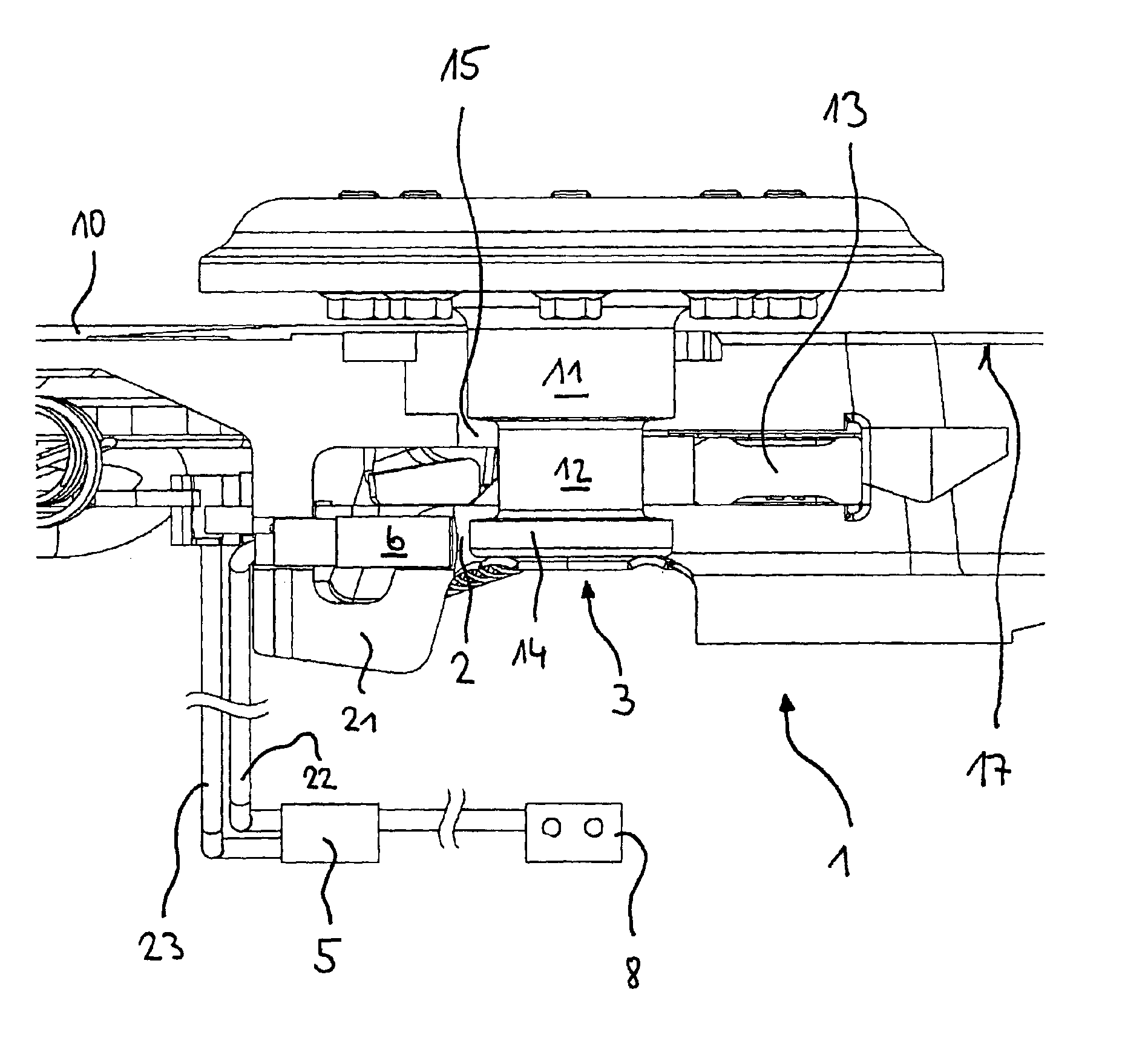
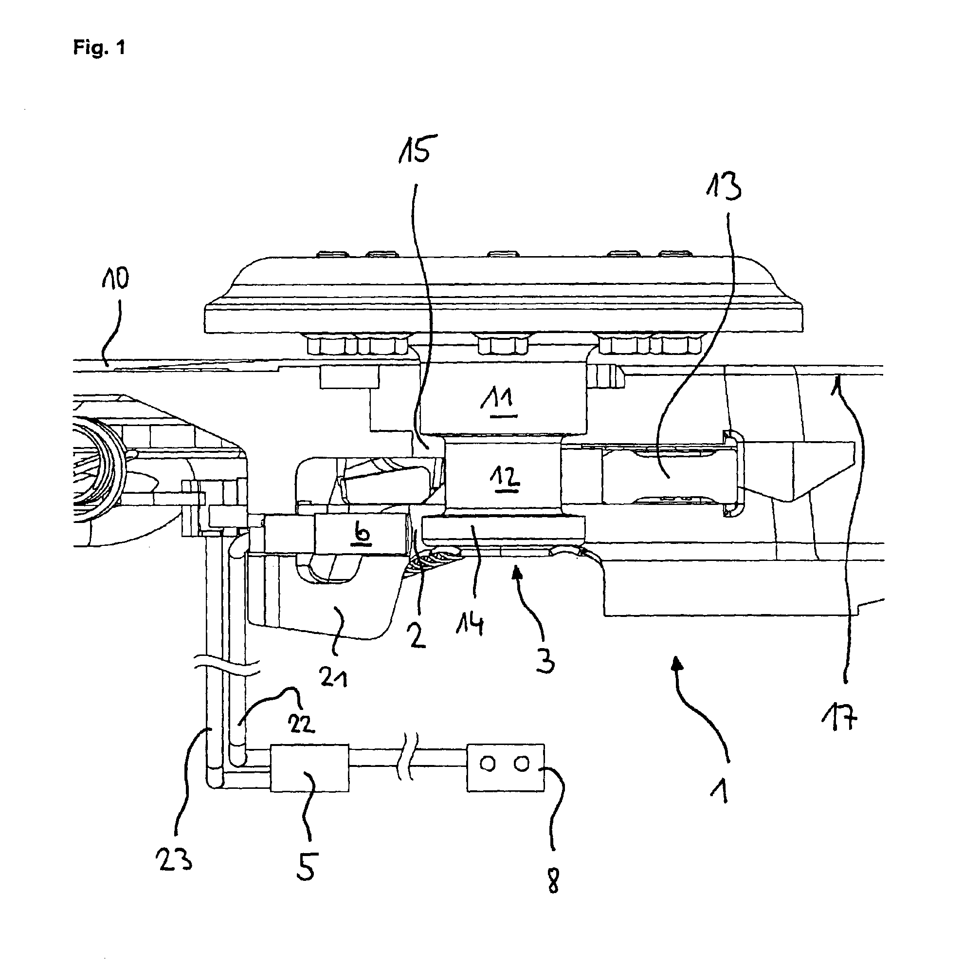
FIG 1 is a longitudinal section of the central area of a fifth wheel 1 with a kingpin 3 arranged in a locating hole 2 (cf. FIG 2). The kingpin 3 essentially has an upper collar 11, a middle section 12 with a reduced diameter below that and a lower collar 14. For a positive locking engagement of the kingpin 3 with the fifth wheel 1, a locking latch 13 pivotably supported on the coupling plate 10 engages with the middle section 12 of the kingpin 3.

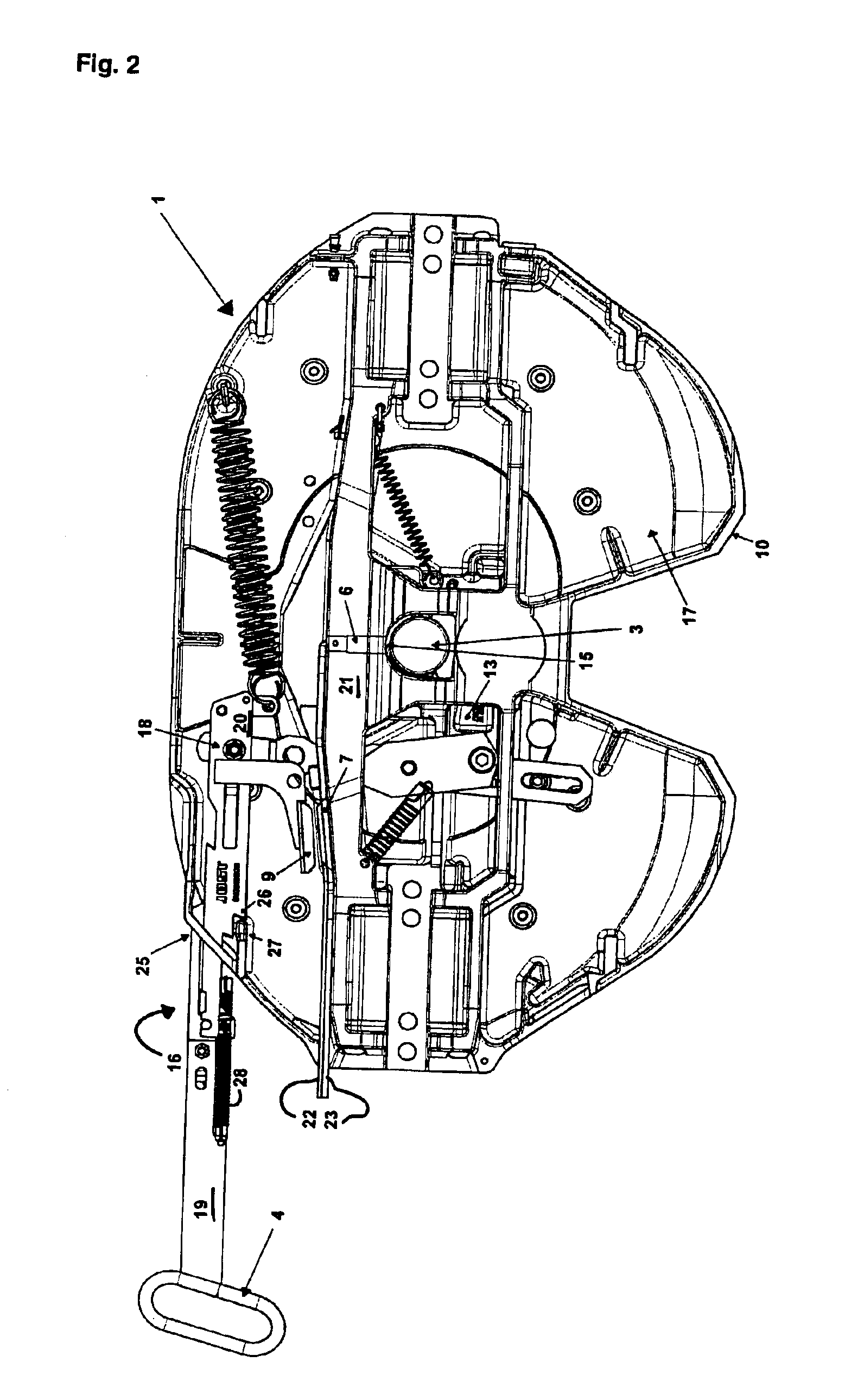
The first sensor 6 is disposed radially to the engaged kingpin 3 in a reinforcing rib 21 where it is protected. It contactlessly detects the lower collar 14 of the kingpin 3 and sends an electrical signal via the first sensor line 22 to the evaluation unit 5. In addition to this first sensor line 22, a second sensor line 23 of the second sensor 7 (see FIG. 2) is connected to the evaluation unit 5. A data line extends from the evaluation unit to e.g. the driver's cab of a tractor (neither of which is shown) where it is connected to a display ...


PUM


Abstract

A device is described for indicating the locking state of a fifth wheel coupling and an arrangement of a first and a second sensor. According to the prior art, the first sensor is arranged on the underside of the locking latch and monitors the position of the kingpin in relation to the locking latch. A second sensor that is used is an inductive proximity switch that monitors a safety mechanism against loosening. In practice, this type of positioning of the first sensor has led to damage of the locking latch and the first sensor, while the signals of the second sensor were often false signals. Thus, the object of the invention is to provide a device for indicating the locking state, which maximizes operational availability and minimizes false signals. A further object of the invention is to optimize the arrangement of the first and the second sensor. These objects are attained by arranging the first sensor detecting the kingpin in the area of the locating hole and configuring the second sensor as a magnetically sensitive sensor that interacts with a magnet mounted on the operating lever. The two sensors are based on different mechanisms of action.

Description

FIELD OF THE INVENTIONThe invention relates to a device for indicating the locking state of a fifth wheel coupling, comprising an evaluation unit to which a first and a second sensor are connected and a display unit which is connected with the evaluation unit. The device further relates to an arrangement of a first and a second sensor on a fifth wheel with which a kingpin in a locked state is engaged in a positive locking manner.BACKGROUND OF THE INVENTIONDE 198 20 139 A1 represents a generic prior art in this connection. This document describes a method and an arrangement for monitoring the proper locking and securing of a fifth wheel equipped with a locking mechanism and a safety mechanism. A first sensor is provided for monitoring the state of the locking mechanism and a second sensor for directly or indirectly monitoring the state of the safety mechanism. The first sensor is an inductive proximity switch and is intended to be mounted on the underside of the locking latch and to ...

Claims


Application Information

Patent Timeline
Patent Type & Authority Patents(United States)
IPC IPC(8): B62D53/10B62D53/00B62D53/08
CPCB62D53/10Y10T292/1082
Inventor ALGUERA, JOSEEIERMANN, MICHAELKRUGER, ACHIM
Owner JOST WERKE
Why Eureka
Try Eureka