
Vehicle seat for aircraft and motor vehicles

a technology for aircraft and motor vehicles, applied in the direction of chairs, sofas, seating arrangements, etc., can solve the problem that the seat in question with its bracing component may be polyfunctional in design, and achieve the effect of increasing seat comfort and increasing cos

Inactive Publication Date: 2005-03-15
RECARO AIRCRAFT SEATING
View PDF28 Cites 33 Cited by
  • Summary
  • Abstract
  • Description
  • Claims
  • Application Information

AI Technical Summary

Benefits of technology

Objects of the present invention are to provide improved vehicle seats for aircraft and motor vehicles with seating comfort increased in the foot and / or leg area, without requiring an appreciable amount of additional space or increased cost.
The foregoing objects are provided when a single support arm is coupled by one free end to the seat frame support and may be locked in assignable positions. The foot and leg rests are mounted each on opposite surfaces of the bracing component pivotally couple the other support arm end. In the areas of the legs of a seat occupant, which require especially efficient support, a combined foot and leg support may be achieved which increases seating comfort and relieves the seat occupant of the task of completing “seating work.” Since both a foot rest and a leg rest are created with only one support component on its opposite surfaces, the solution involved may also be applied cost effectively and with conservation of space. A contribution to this solution is also made by the circumstance that the support arm with integrated foot and / or leg rest preventing, as demonstrated in the state of the art, supporting of an entire leg as a sort of couch, accompanied by formation of a total supporting surface.
In another preferred embodiment of the vehicle seat of the present invention, the foot rest is provided with raised areas such that a sort of massage function is performed for the particular seat occupant. In this way, the comfort of the seat occupant is distinctly improved, especially in the event of protracted occupation of the seat during an airplane or bus trip.

Problems solved by technology

As a result, the rest in question with its bracing component may be polyfunctional in design.

Method used


Image

  • Vehicle seat for aircraft and motor vehicles
  • Vehicle seat for aircraft and motor vehicles
  • Vehicle seat for aircraft and motor vehicles

Examples


Embodiment Construction

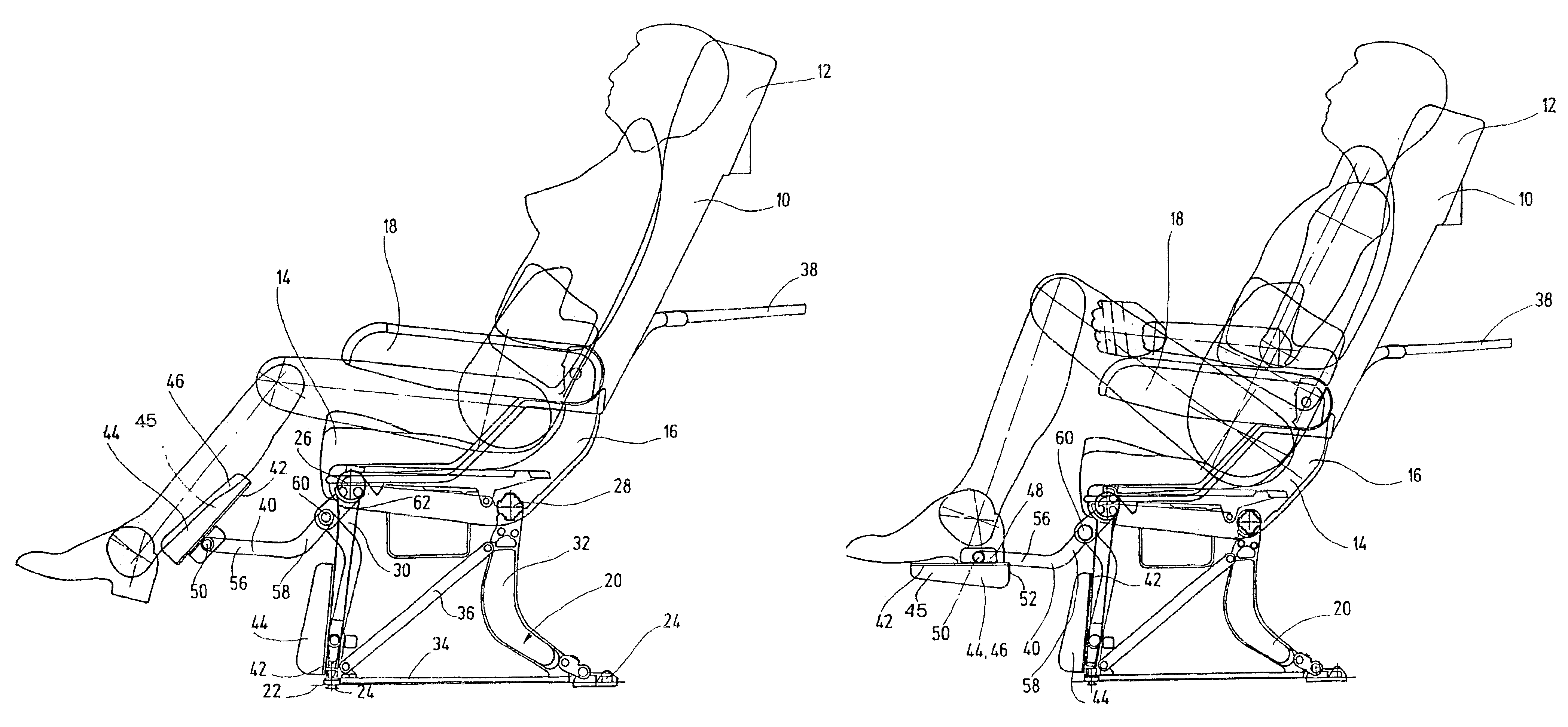
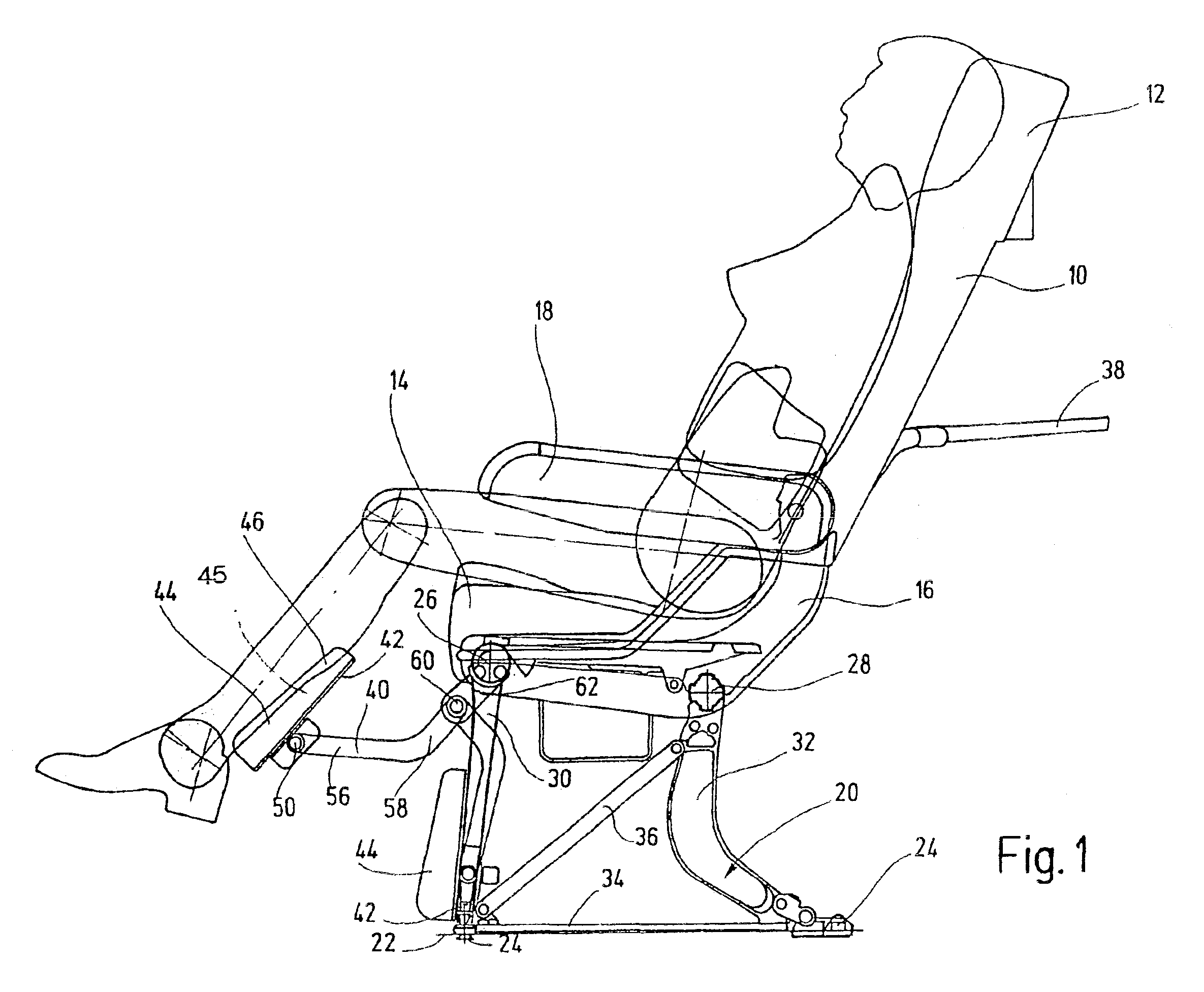
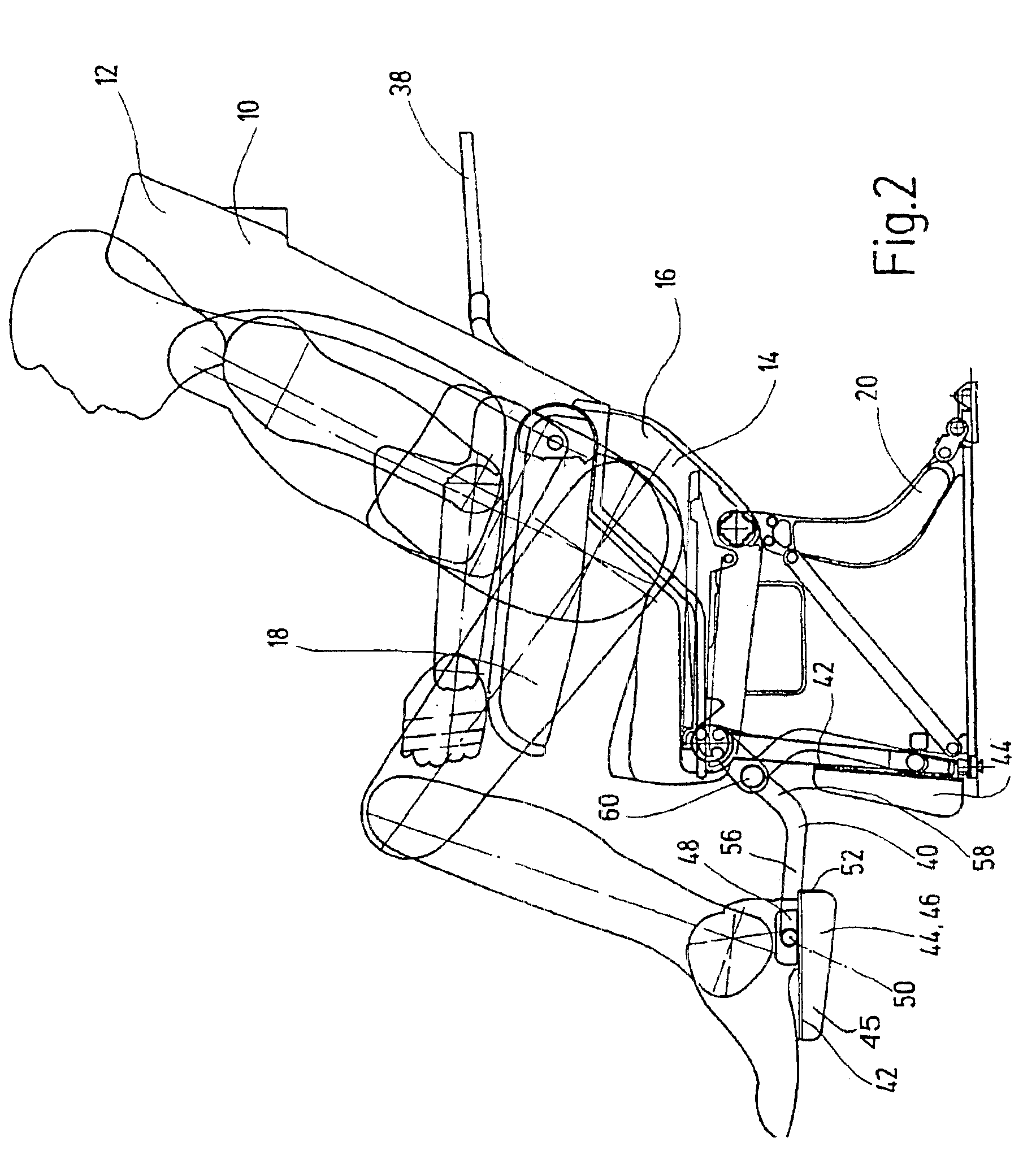
The vehicle seat, an aircraft seat in particular, shown in FIG. 1 has an adjustable-inclination back rest 10 with integrated head rest 12. In its lower part, back rest 10 effects transition to the seat component or thigh rest 14, in which a female occupant, represented in outline, has been seated in the seat illustrated. The seat component 14 is accommodated by a seat shell 16, preferably of a plastic material, and has at least one tilting arm rest 18. To enhance seating comfort, arm rest 18 is in its lowered passenger position in the illustration in FIG. 1. The seat shell 16 and accordingly the seat component 14 rest on a seat frame support 20 which permits fastening of the vehicle seat to a vehicle floor 22 by suitable fastening means 24. The fastening means, as well as the structure of the seat frame support 20, are conventional and thus will not be described further in detail.

The seat frame support 20 includes a front cross brace 26 and rear cross brace 28 in the area of the bac...


PUM


Abstract

A vehicle seat for aircraft and motor vehicles, includes a back rest (10) and a seat part (14) supported by a seat frame connected to a vehicle floor. One support arm (40) pivotally supports on one of its ends a combined foot (42) and leg support (44) as separate surfaces of a bracing component (45). The support arm (40) is coupled to the seat frame (20) at its other free end in a pivotable manner and may be adjusted detent-wise through preset positions. The foot (42) and the leg support (44) are arranged on opposite faces of the support piece (45).

Description

FIELD OF THE INVENTIONThe present invention relates to a vehicle seat for aircraft and motor vehicles with a back rest and a seat component retained by a seat frame support connected to the vehicle floor. One support arm has pivotably mounted on its one free end a combined foot and leg rest, as opposite surfaces of a bracing component. The foot rest is employed exclusively in one pivoting position. The leg rest is employed in another pivoting position.BACKGROUND OF THE INVENTIONVehicle seats, air passenger seats or motor passenger seats in particular, are known in a plurality of embodiments. Modern vehicle seats have a large number of possible settings for the seat component and the back rest. In addition, good upholstery and arm rests increasing comfort are currently included in the standard.Regarding leg comfort, however, much remains to be desired. While high-quality vehicle seats such as are used in first class or business class, also have leg rests, the leg and foot area has be...

Claims


Application Information

Patent Timeline
Patent Type & Authority Patents(United States)
IPC IPC(8): A47C7/50A47C7/00B60N2/44B60N3/06B60N3/00B64D11/06B64D11/00B60N2/90
CPCB60N2/4495B60N3/063B64D11/0643B64D11/064B64D11/06Y10S5/944B60N2/995
Inventor BEHNERT, ECKHARD
Owner RECARO AIRCRAFT SEATING
Learn More