Ink jet recording apparatus, and method of supplying ink to sub-tank of the ink jet recording apparatus

a technology of ink jet recording apparatus and ink jet, which is applied in printing and other directions, can solve the problems of inability to supply ink to the sub-tank by ink cartridge, erroneous detection of low ink state, etc., and achieve the effect of preventing erroneous detection of ink quantities

Inactive Publication Date: 2005-03-15
SEIKO EPSON CORP
View PDF11 Cites 38 Cited by
  • Summary
  • Abstract
  • Description
  • Claims
  • Application Information

AI Technical Summary

Benefits of technology

[0020]To resolve the above technical problems, it is one objective of the present invention to provide an ink jet recording apparatus that can set a satisfactory long interval for the supply of ink to sub-tanks and can thus prevent the erroneous detection of the ink quantities in the sub-tanks, which is caused by a factor such as vibration, and a control method for supplying ink to the sub-tanks of the ink-recording apparatus.
[0054]Through the exercise of this control, the supply of ink to the sub-tank is initiated when it has been confirmed that a predetermined quantity of the ink in the sub-tank has been consumed. Thus, a problem involving the frequent, repeated resupply of ink from the ink cartridge to the sub-tank can be avoided, and a satisfactorily long interval can be obtained for the supply of ink to the sub-tank.
[0055]Since the supply of ink to the sub-tank is controlled, the erroneous detection of the quantity of ink in the sub-tank, which is the result of vibration or another factor, can be prevented, and the quantity of ink in the sub-tank can be constantly maintained within a specific range. Thus, a normal printing operation can be continuously performed.
[0056]The predetermined ink quantity total is set for the ink consumption counter to establish a relationship wherein the quantity of ink ejected by the recording head in the printing operation+the ink quantity ejected from the recording head by the flashing operation+the ink quantity discharged from the recording head by one cleaning operation<the effective ink quantity in the sub-tank”. Therefore, even when the printing of a predetermined quantity of data, a flushing operation and one cleaning operation are performed following the supply of ink to the sub-tank, the ink in the sub-tank would not be exhausted, so that the problem that would arise were air to enter an empty ink flow path leading from a sub-tank to the recording head can be avoided.

Problems solved by technology

In this case, because of an above described factor, such as the rippling of ink in the sub-tank or an external vibration, a low ink state may be erroneously detected even though the sub-tank is full of ink.
Therefore, when the ink quantity total held by the ink consumption counter has not reached a predetermined ink quantity total even though the ink level detector has detected a low ink state, it can be assumed that either a very small quantity of ink has been consumed, or an erroneous detection by the ink level detector has occurred.
Thus, in this case, the supply of ink to the sub-tank by the ink cartridge is inhibited.

Method used


Image

  • Ink jet recording apparatus, and method of supplying ink to sub-tank of the ink jet recording apparatus
  • Ink jet recording apparatus, and method of supplying ink to sub-tank of the ink jet recording apparatus
  • Ink jet recording apparatus, and method of supplying ink to sub-tank of the ink jet recording apparatus

Examples


Embodiment Construction

DESCRIPTION OF THE DRAWINGS

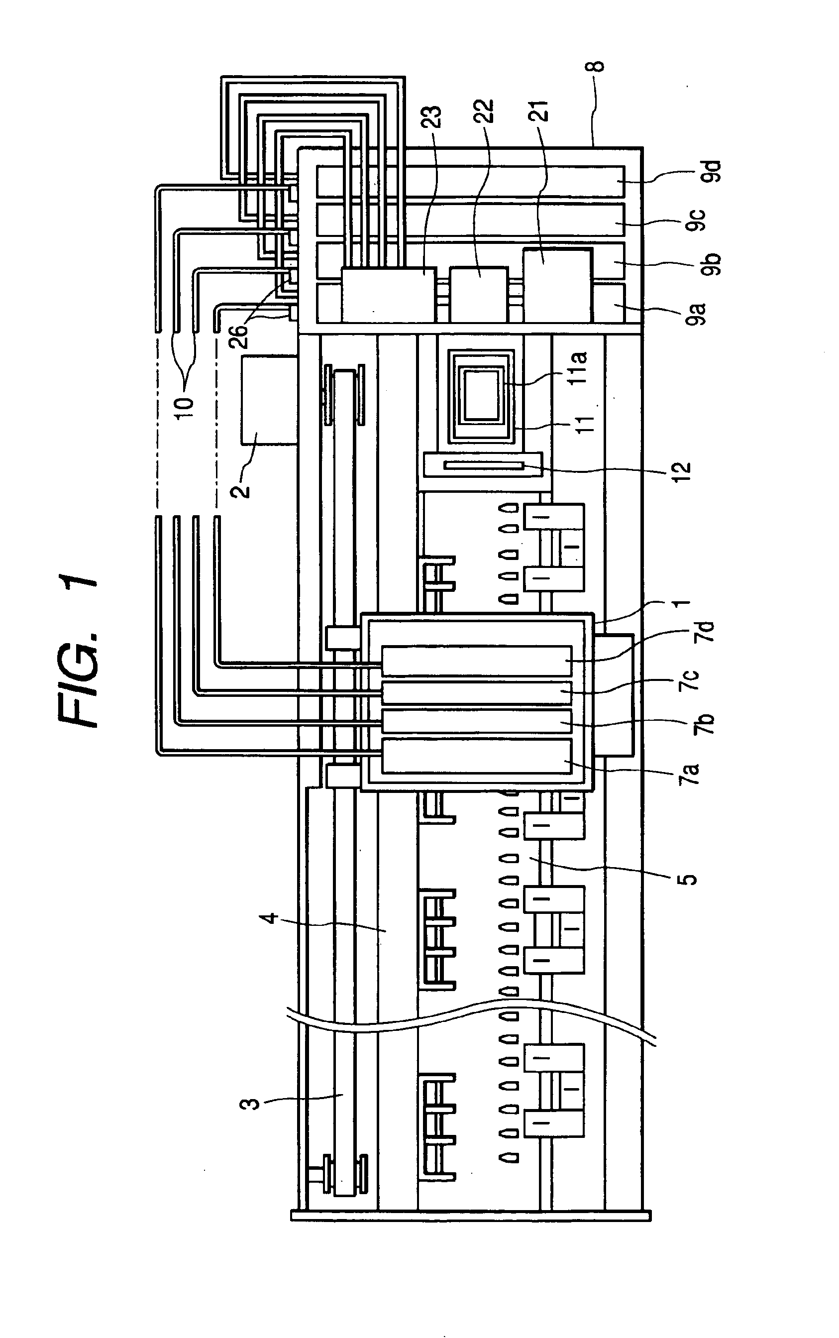
[0057]FIG. 1 is a plan view of the basic arrangement of an ink jet recording apparatus according to the present invention.

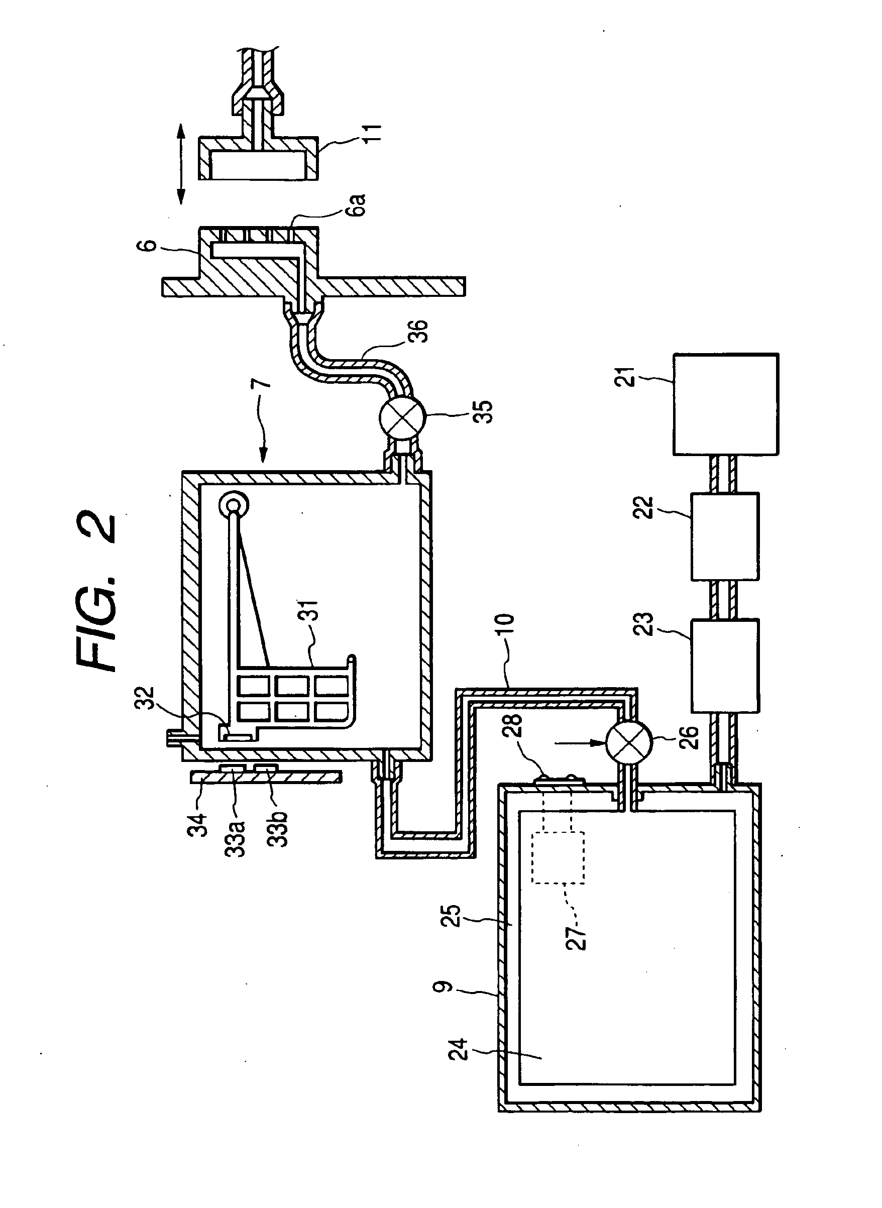
[0058]FIG. 2 is a specific diagram showing an ink supply system ranging from an ink cartridge to a recording head.

[0059]FIG. 3 is a partially cutaway, perspective view of a sub-tank viewed from one plane direction.

[0060]FIG. 4 is a perspective side view of the sub-tank viewed in the same plane direction.

[0061]FIG. 5 is a partial cross-sectional view of the state wherein the pressure control valve that is used is a pressure control valve that also serves as a relief valve.

[0062]FIG. 6 is a partial cross-sectional view of the air release state obtained by the relief operation.

[0063]FIG. 7 is a block diagram showing a control circuit that constitutes a part of the means for supplying ink to the sub-tank that implements the method of the invention.

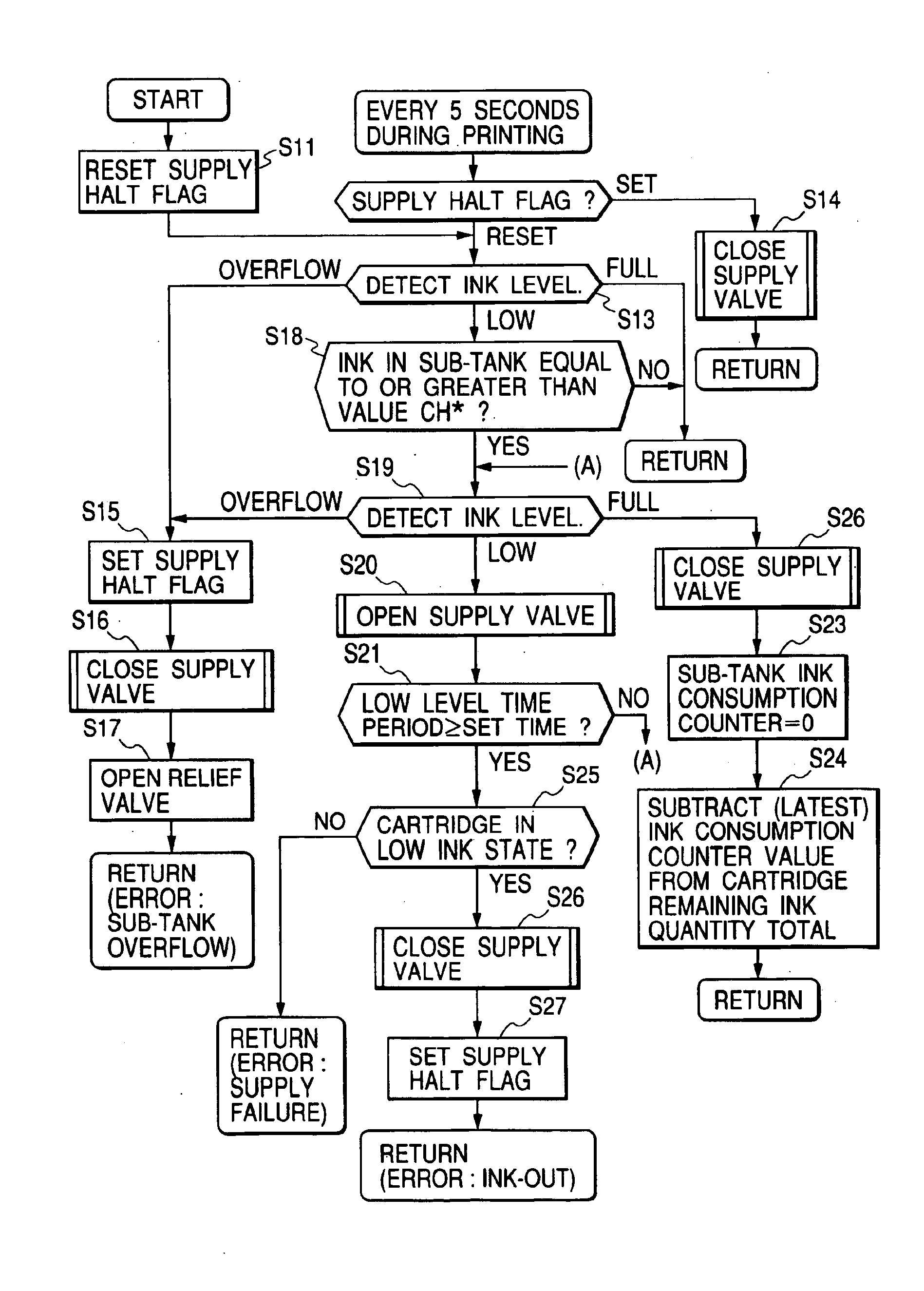
[0064]FIG. 8 is a flowchart showing the control routine for the method of the invention for su...


PUM


Abstract

Ink from an ink cartridge is supplied along an ink supply tube to a sub-tank mounted on a carriage. Provided for the sub-tank is an ink level detector constituted by a float member on which a permanent magnet is mounted, and Hall devices. Further, a ink consumption counter is also included for calculating the quantity of ink ejected or discharged by a recording head. When a low ink state is detected by the ink level detector and when the value held by the ink consumption counter has reached a predetermined ink quantity total, the supply of ink from the ink cartridge to the sub-tank is initiated.

Description

BACKGROUND OF THE INVENTION[0002]The present invention relates to an ink jet recording apparatus wherein sub-tanks for supplying ink to a recording head are mounted on a carriage, and relates in particular to an ink jet recording apparatus that can control, within an appropriate range, the quantity of ink retained in each sub-tank and to a method of supplying ink the sub-tanks of the ink jet recording apparatus.[0003]A related ink jet recording apparatus of a serial printing type is provided with: an ink jet recording head, which is mounted on a carriage and is moved in a width direction of a recording sheet; and a paper feeding unit, for moving the recording sheet in a direction perpendicular to the width direction in which the recording head is moved. Based on printing data, the ink jet recording apparatus, when printing, ejects ink droplets from the recording head onto a recording sheet.[0004]For this type of recording apparatus, which is provided for office or for professional u...

Claims


Application Information

Patent Timeline
Patent Type & Authority Patents(United States)
IPC IPC(8): B41J2/175B41J2/18B41J2/185
CPCB41J2/17509B41J2/17566B41J2002/17576
Inventor ARUGA, YOSHIHARUKOBAYASHI, ATSUSHIKUMAGAI, TOSHIO
Owner SEIKO EPSON CORP
Why Eureka
Try Eureka