Projection device
- Summary
- Abstract
- Description
- Claims
- Application Information
AI Technical Summary
Benefits of technology
Problems solved by technology
Method used
Image

Examples
first preferred embodiment
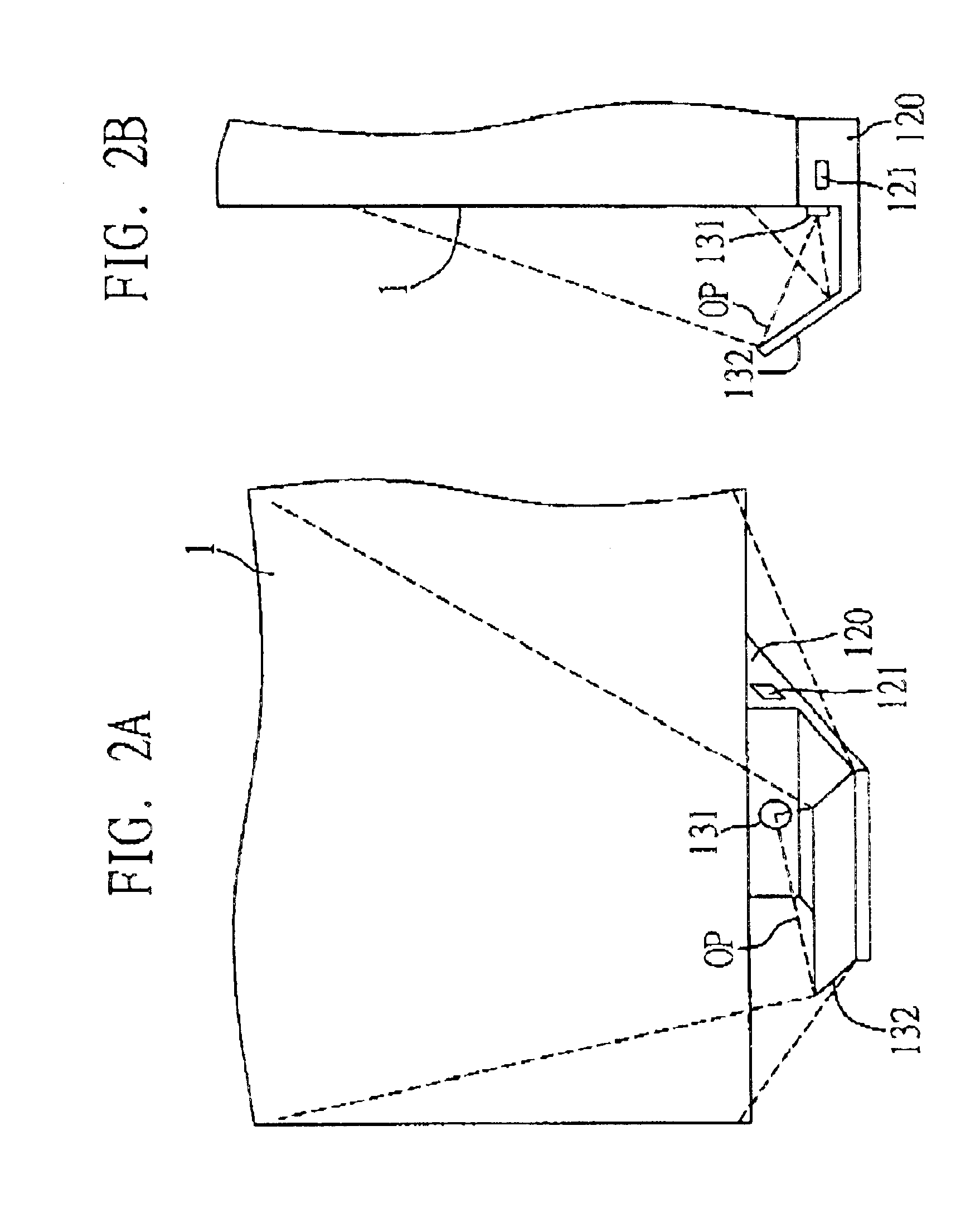
FIGS. 2A and 2B illustrate front and side views of a projection device according to a first preferred embodiment of the invention. As shown in the drawings, this projection device having a projection module 120 is installed on a bottom side of a display area 1 for displaying an optical image. The projection device comprises at least one projection module 120. It should be understood that the projection device may alternatively be mounted on a left, right or top side of the display area 1 depending on practical requirements. The display area 1 can be a wall, a whiteboard, a digitizing tablet, or any other suitable surface for image display.
In this embodiment, the projection module 120 has a communication interface 121, an optical lens 131 (having at least a convex lens) with an optic axis directed toward a same direction as the display area 1, and an optical reflector 132 formed on the optic axis of the optical lens 131. The projection module 120 can be connected via the communicatio...
second preferred embodiment
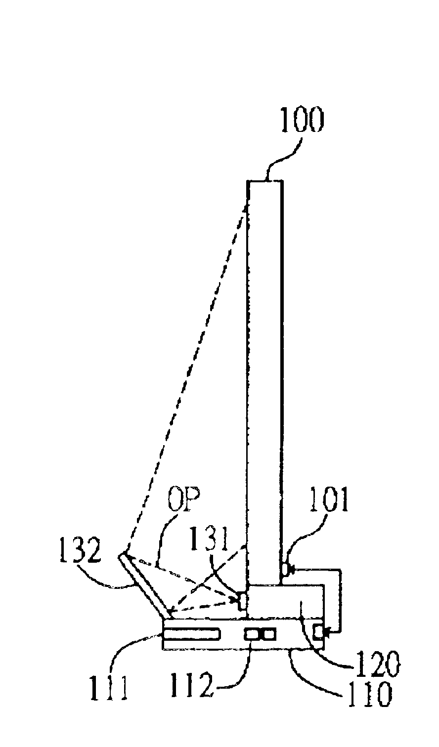
FIGS. 3A and 3B illustrate front and side views of the projection device according to a second preferred embodiment of the invention. As shown in the drawings, this projection device is connected to a digitizing tablet 100, and at least includes a computer 110 and a projection module 120.
The digitizing tablet 100 has a connection interface 101, such as a standard wired RS-232 interface, for connecting the digitizing tablet 100 to the computer 110. characteristic feature of the invention is to use internal circuits for the connection between the digitizing tablet 100 and the computer 110, thereby not having to use inconvenient external cables.
The computer 110 is a data processing module such as a RISC (reduced instruction set computing) unit which can execute various data processing functions, for example to process data to be displayed on the digitizing tablet 100. Furthermore, the computer 110 can be further formed with a data storage unit 111 (such as DVD-ROM drive, CD-ROM drive, ...
third preferred embodiment
FIGS. 4A and 4B illustrate front and side views of the projection device according to a third preferred embodiment of the invention. This projection device is connected to a digitizing tablet 200, and at least includes a computer 210 and a projection module 220.
Similarly to the above second preferred embodiment, the digitizing tablet 200 may have a connection interface 201 for connecting the digitizing tablet 200 to the computer 210, and may further include a data storage unit 211 (such as DVD-ROM drive, CD-ROM drive, hard disk drive, floppy disk drive, etc.) and a communication interface 212 (such as USB, RS-232, PS / 2, etc.).
A characteristic feature of this embodiment is that the projection module 220 has an optical lens 231 only but not with an optical reflector, wherein an optic axis of the optical lens 231 is directed at a predetermined angle toward the digitizing tablet 200, so as to allow an optical image to be directly projected by the optical lens 231 on the digitizing table...
PUM
 Abstract
Description
Claims
Application Information
 - R&D
- Intellectual Property
- Life Sciences
- Materials
- Tech Scout
- Unparalleled Data Quality
- Higher Quality Content
- 60% Fewer Hallucinations
Browse by: Latest US Patents, China's latest patents, Technical Efficacy Thesaurus, Application Domain, Technology Topic, Popular Technical Reports.
© 2025 PatSnap. All rights reserved.Legal|Privacy policy|Modern Slavery Act Transparency Statement|Sitemap|About US| Contact US: help@patsnap.com