Apparatus and method for producing ambulatory motion

a technology of apparatus and motion, applied in the direction of toys, dolls, remote-control toys, etc., can solve the problems of loss of traction, difficulty in achieving stable devices, and complex mechanical and control systems, and achieve good stability and control characteristics

Inactive Publication Date: 2005-03-15
RANDALL MITCH
View PDF21 Cites 96 Cited by
  • Summary
  • Abstract
  • Description
  • Claims
  • Application Information

AI Technical Summary

Benefits of technology

Accordingly, an object of the present invention is to provide relatively simple leg-like systems that can propel objects with ambulatory motion with good stability and control characteristics for any of a variety of objects; for example, but not for limitation, toys, robotic vehicles, amusement devices, transportation, weapons systems, etc.

Problems solved by technology

However, problems persist in achieving stable devices with minimum complexity in the mechanical and control systems.
However, for simpler, articulated and unarticulated mechanical leg structures, any one or all of such bobbing, weaving, and surging motions become impulses that can cause chattering, loss of traction, and loss of control, even to the extent of knocking the object off balance, off track, and / or off the floor, ground, or other supporting surface or even tipping it over.
Such bobbing and weaving can also dissipate energy, thereby reducing efficiency, and inefficient slippage of the legs on the supporting surface is also a problem, especially for systems in which the leg-like structures move at varying speeds in relation to the object and support surface during a step cycle.

Method used


Image

  • Apparatus and method for producing ambulatory motion
  • Apparatus and method for producing ambulatory motion
  • Apparatus and method for producing ambulatory motion

Examples


embodiment 12

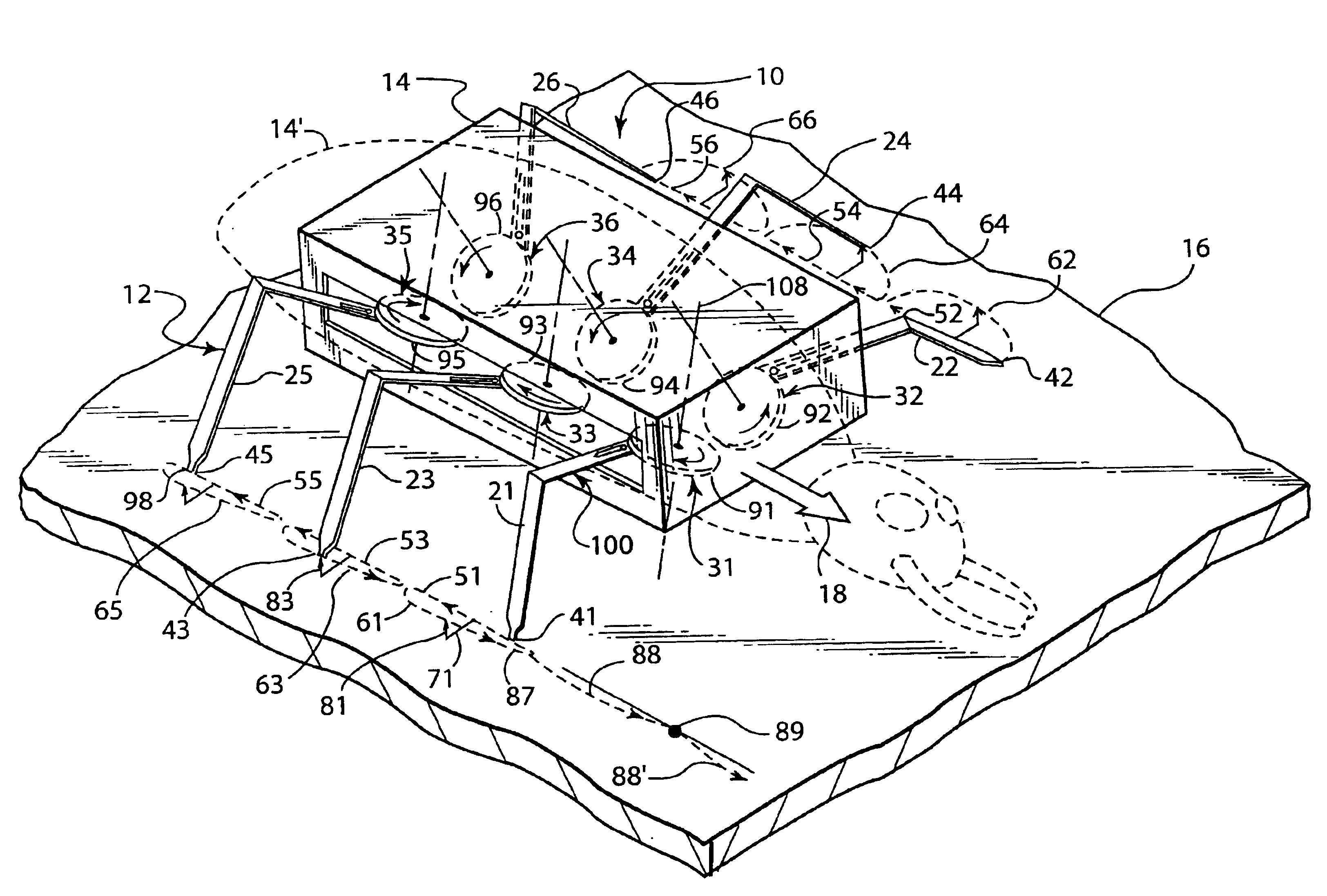
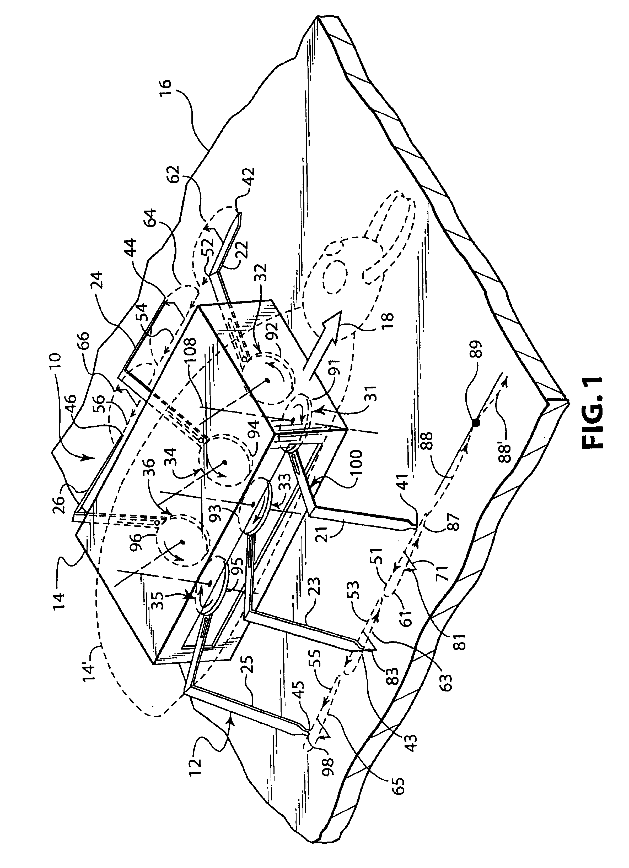
In the example ambulatory leg system embodiment 12 shown in FIG. 1, the cyclic path of the foot 41, which is typical of the respective cyclic paths of the other feet 42, 43, 44, 45, 46, has its rectilinear path 51 of the stride stroke illustrated in phantom lines on the support surface 16. This view of the stride stroke 51 is accurate when viewing the path of the stride stroke 51 in relation to the body 14. Also, the step stroke.61 in the example embodiment of FIG. 1, when viewed in relation to the body 14, moves the foot 41 in the arcuate path of the step stroke 61, which extends outwardly 71 and upwardly 81 in relation to the body 14. However, because the body 14 is propelled forwardly, as indicated by the arrow 18, when the feet 41, 42, 43, 44, 45, 46 are driven in the respective stride strokes 51, 52, 53, 54, 55, 56, as shown in FIG. 1, the apparent depiction of the stride strokes 51, 52, 53, 54, 55, 56 as straight lines having lengths on the support surface 16 is not really acc...

embodiment 10

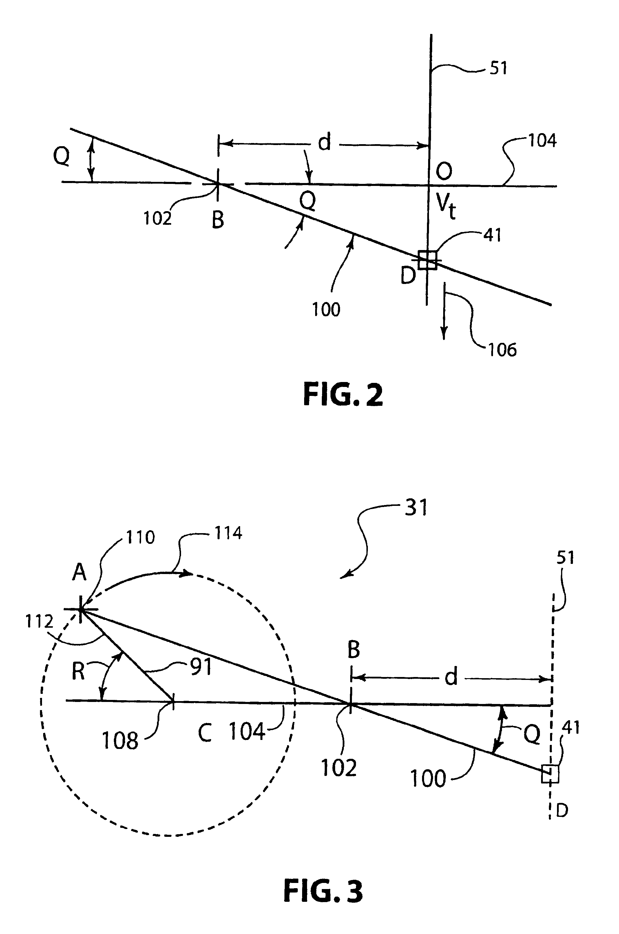
Also, as mentioned above, for stability, it is preferred that several of the feet 41, 42, 43, 44, 45, 46—at least two on one side of the body 14 and at least one on the other side of the body 14—be somewhere in their respective stride strokes at the same time so that at least three feet are supporting the object 10 on the surface 16 in a tripod (triangle) relationship to each other at any particular instant in time. Therefore, while each leg strut 21, 22, 23, 24, 25, 26 of the example embodiment shown in FIG. 1 is driven with its own respective crank-type drive mechanism 31, 32, 33, 34, 35, 36, as will be described in more detail below, some phase coordination among them is preferred for such stability purposes. For one example, as illustrated in FIG. 1, on the right side of the object 10, the right front foot 41 is planted at a spot 87 on the surface 16 and is just beginning its stride stroke 51 as the right rear foot 45 is also planted at a spot 98 on the surface 16, but nearing t...

embodiment 160

A modified 4-legged device 160 equipped with two additional faux legs 155, 156 connected by a pivotal cross axle 157 is shown in FIGS. 29-33. This embodiment 160 can move straight forward rapidly and smoothly and turn in reverse without tipping on a reasonably smooth support surface. When the device 160 moves forwardly, the two faux legs 155, 156 drag lightly and do not interfere with the normal stride 158 and stepping 159 strokes of the four legs 151, 152, 153, 154. However, when the four legs 151, 152, 153, 154 are operated in reverse, the right side faux leg 155, which is longer than the left side faux leg 156 and longer than the regular legs 151, 152, 153, 154, engages the support surface and raises the right side of the device 160 enough to lift the right legs 151, 153 off the support surface, thereby becoming a pivot point about which the surface engaging legs will turn the device 160.

As best seen in FIG. 30, the two faux legs 155, 156 are connected by the axle 157, which exte...


PUM


Abstract

An ambulatory mechanical leg system drives a mechanical leg (100, 21) with a crank (91) to pivot about a pivot axis (102) to produce uniform rectilinear motion at the distal end (41) of the leg (100, 21) during a stride stroke (51) portion of a crank revolution or cycle and then lifts the distal end (41) to fast-return it in a step stroke (61) during the remainder of the revolution to a starting point for the next stride stroke (51). The crank (91), leg (100, 21) and pivot axis (102) sizes and proportional lengths or distances are modeled to an angular profile that produces nearly constant velocity, and mechanical structures maintain nearly rectilinear motion, of the distal end (41) of the leg (100, 21) during the stride stroke (51).

Description

BACKGROUND OF THE INVENTION1. Field of the InventionThis invention is related to systems that simulate ambulatory propulsion of objects on leg-like motive structures and, more specifically, to leg-like structures and associated drive systems that produce uniform rectilinear motion of such leg-like motive structures to propel objects in a stable and controllable manner over a support surface.2. Brief Description of the Prior ArtThere have been many attempts to make leg-like mechanical systems for propelling objects ranging from robotic vehicles to toy bugs, and some of them are capable of performing that function. However, problems persist in achieving stable devices with minimum complexity in the mechanical and control systems. For example, many of the prior art leg-like mechanical structures, especially non-articulated and simpler articulated leg-like mechanical structures, impart some amount of bobbing (up and down) motion and / or weaving (side to side) motion and / or surging (forwa...

Claims


Application Information

Patent Timeline
Patent Type & Authority Patents(United States)
IPC IPC(8): A63H11/00A63H11/20B62D57/00B62D57/02B62D57/032
CPCA63H11/205B62D57/032B62D57/02
Inventor RANDALL, MITCH
Owner RANDALL MITCH
Why Eureka
Try Eureka