Fluid flow control valve with composition seal

a technology of composition seal and flow control valve, which is applied in the direction of plug valves, valve details, valve arrangements, etc., can solve the problems of increasing frictional forces between the ball element and the seal assembly, affecting the life of the valve components, and affecting the service life of the valv

Inactive Publication Date: 2006-10-19
FISHER CONTROLS INT LLC
View PDF22 Cites 24 Cited by
  • Summary
  • Abstract
  • Description
  • Claims
  • Application Information

AI Technical Summary

Benefits of technology

[0006] Therefore, there remains a need for an improved ball valve having a seal assembly and a ball element that is capable of bi-directional sealing of the fluid, that is able to reduce the wear between the main seal and the ball element, that retains positive dynamic performance and control characteristics, and that prevents fibrous material or particles from being trapped between the ball element and the main seal.

Problems solved by technology

During operation of the valve, many components suffer wear due to repeated and extensive cycling of the valve, specifically the ball element and seal assembly, due to continuous frictional contact during the opening and closing of the valve.
The problems resulting from the wear include, but are not limited to, diminished life span of the valve components, increased frictional forces between the ball element and the seal assembly, and undesirable leakage between the ball element and the seal assembly.
Similarly, as the frictional forces relatively increase with the amount of wear the components experience, the dynamic performance and control characteristics within the valve are worsened, resulting in inefficiencies and inaccuracies in the valve.
This, however, has resulted in limiting the applications of the valve, including constraining the valve to limited bi-directional sealing capabilities.
Furthermore, with the additional force and pressure created by the biased main seal against the ball element, additional wear between the ball element and the seal assembly, and specifically the main seal, is created.
This, however, has resulted in further complications, such as trapping debris between the ball element and the main seal.
For example, when the media traveling through the valve contains fibrous material such as pulp stock or particles, the fibrous material may be trapped between the ball element and the main seal during the closing of the valve, effectively creating a leak path through the valve.

Method used


Image

  • Fluid flow control valve with composition seal
  • Fluid flow control valve with composition seal
  • Fluid flow control valve with composition seal

Examples


Embodiment Construction

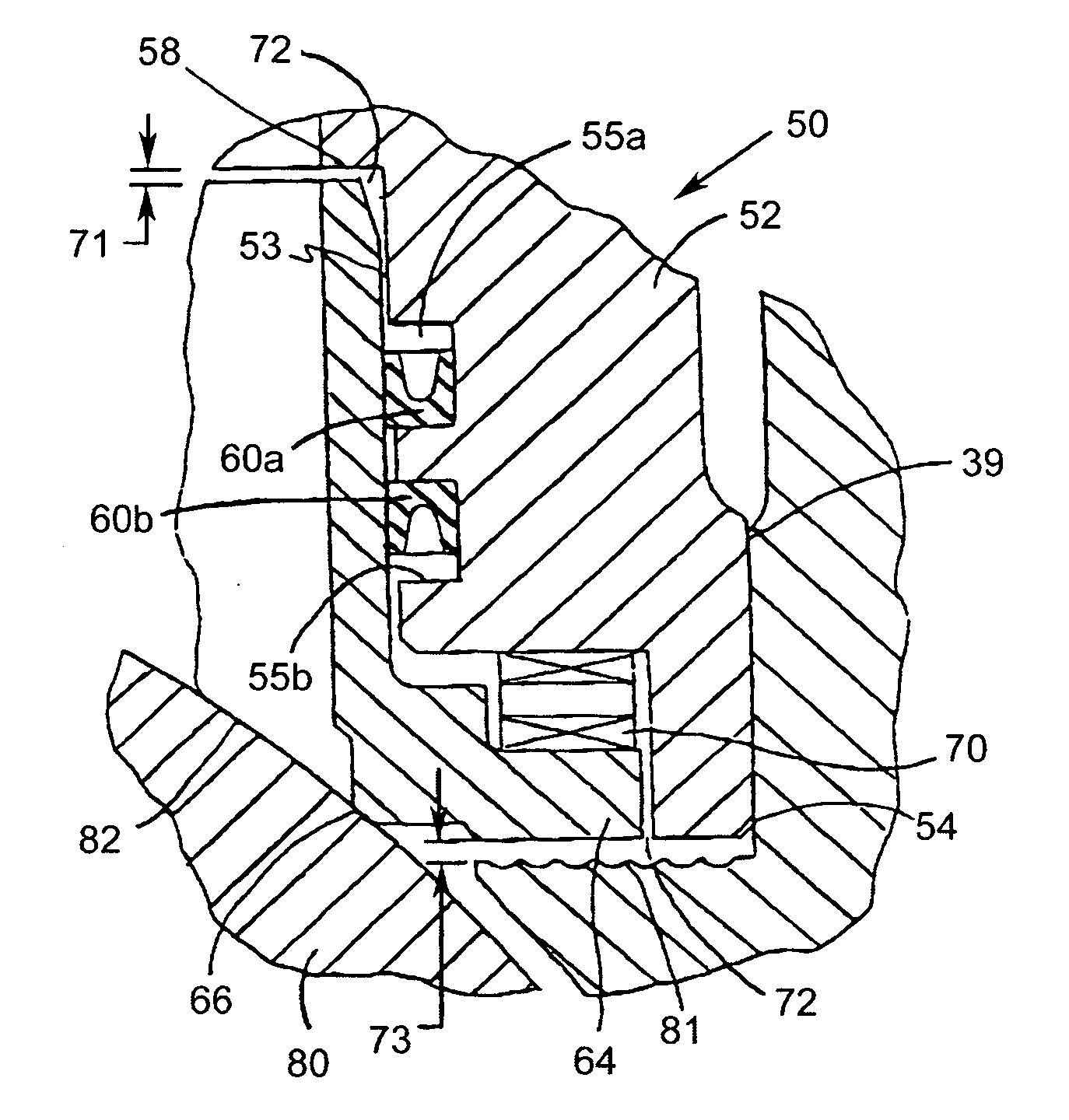
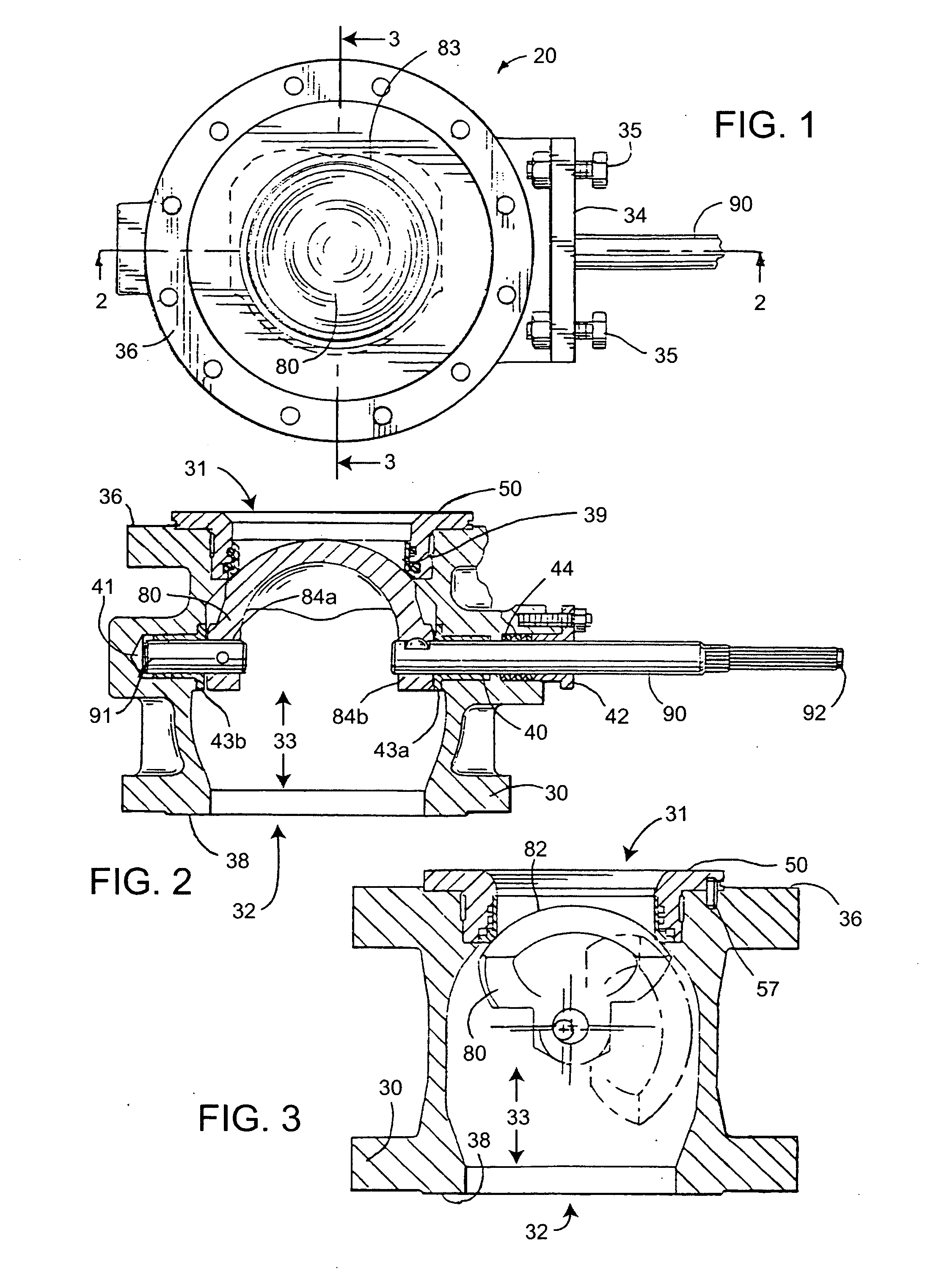
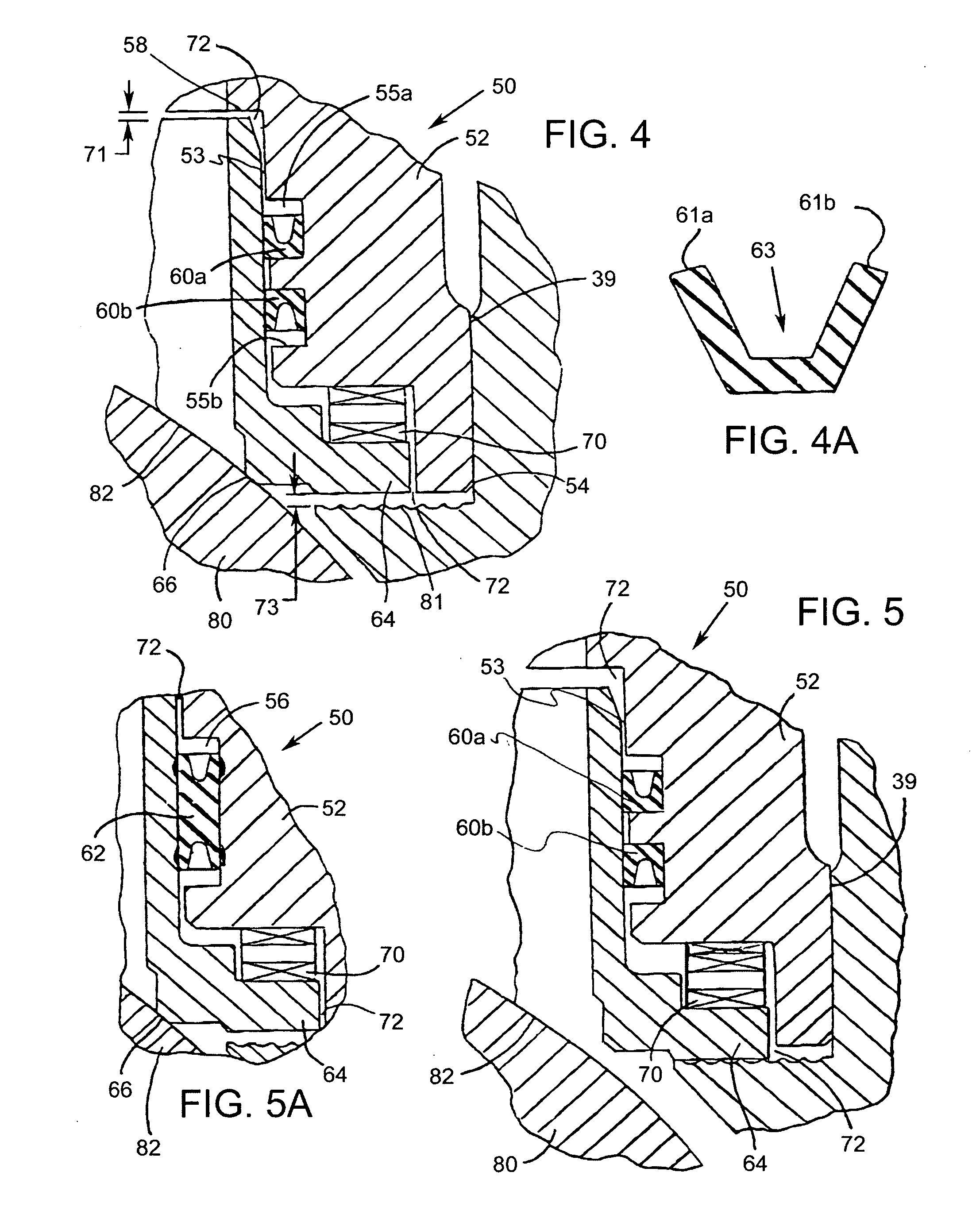
[0024] Referring now to the drawings, and with specific reference to FIGS. 1-3, a ball valve constructed in accordance with the teachings of the disclosure is generally depicted by reference numeral 20. As shown therein, the ball valve 20 includes a housing. 30 having a primary flowpath 33 between an inlet 31 and an outlet 32, a seal assembly 50 and a ball element 80 mounted on rotatable shafts 90 and 91.

[0025] The housing 30, generally having a cylindrical shape, defines the primary flowpath 33 for a fluid traveling therethrough. At the bottom of the housing 30, as oriented in FIG. 2, is the outlet 32, of the primary flowpath 33, the outlet 32 being surrounded by an outlet flange 38. In the middle portion of the housing 30, a thru hole 40 penetrates the right wall of the housing 30, and a blind hole 41 opens to the interior of the housing 30, both holes 40 and 41 being concentric to each other and adapted to receive the shaft 90 and 91, respectively. A packing follower 42, a set o...


PUM


Abstract

A control valve of the ball type is disclosed. The valve includes a housing having an inlet and an outlet in fluid communication with a bore that defines a primary flowpath. A ball element is mounted in the housing and is adapted to move between a closed position, fluidically disconnecting the inlet from the outlet, and an open position, fluidically connecting the inlet and outlet. A seal assembly is disposed within the housing and includes a seal housing and a biased main seal. The biased main seal includes an insert that engages the ball element during the opening and closing of the valve.

Description

FIELD OF THE DISCLOSURE [0001] The disclosure relates to fluid valves and, more particularly, to fluid valves of the ball-type having a composition seal. BACKGROUND OF THE DISCLOSURE [0002] Ball valves are used in a wide number of process control system applications to control some parameter of a process fluid (this may be a liquid, gas, slurry, etc.). While the process control system may use a control valve to ultimately control the pressure, level, pH or other desired parameter of a fluid, the control valve basically controls the rate of fluid flow. [0003] Typically, a ball valve may include a fluid inlet and a fluid outlet separated by a ball element which, by rotating about a fixed axis and abutting to a seal assembly, controls the amount of fluid flow therethrough. During operation, the process control system, or an operator controlling the control valve manually, rotates the ball element against a surface of the seal assembly, thereby exposing a flow passage, to provide a desi...

Claims


Application Information

Patent Timeline
Patent Type & Authority Applications(United States)
IPC IPC(8): F16K25/00
CPCF16K5/0678F16K1/2071F16K1/2266
Inventor WITT, GARY A.
Owner FISHER CONTROLS INT LLC
Why Eureka
Try Eureka