Doctor device

a technology of a doctor and a holder, which is applied in the direction of liquid surface applicators, application substance rearrangement, coatings, etc., can solve the problems complicated and relatively long cleaning procedures, and the installation and removal of a large number of tubes, so as to achieve the effect of simple device basic structure, good possible variations, and good accessibility

Active Publication Date: 2013-04-16
VOITH PATENT GMBH
View PDF43 Cites 0 Cited by
  • Summary
  • Abstract
  • Description
  • Claims
  • Application Information

AI Technical Summary

Benefits of technology

[0011]The present invention provides a doctor device of modular design, which means that all the components that are susceptible to wear can easily be interchanged with one another. In addition, improved flexibility is therefore achieved as a result of possible variations of clamping and pressure tube, bottom part and top part, with regard to material, form, thickness selection and so on.
[0012]The modular design permits ideal degrees of configuration freedom, it being possible to select diameters and shapes of different size of the pressing and clamping tube, which means that a different introduction of force and control characteristic is possible. For example, a metering rod having a small diameter would be assigned a pressure tube of likewise smaller dimension and, with the same effect, a large rod diameter would be assigned a large tube. In addition, different tube displacements, which signify different actuating travels, and also different tube geometries which form other travel-force characteristic curves, can be implemented by way of simple combination and replacement of the components kept ready.
[0013]The modular design of the present invention permits many and various possible combinations between the top and the bottom part to the desired extent. For example, it is possible to place on the same bottom part a top part which has a different size of a holding area (rod holder) for another selected metering rod diameter and / or also has a different holder for other geometries and contours of the pressure tube. Optimized service lives of the components of the doctor device are thus possible.

Problems solved by technology

The installation and removal of the tube or also of a large number of tubes, as well as the cleaning of the device, are complicated and relatively lengthy.
In some designs, the clamping tube is subjected to a high level of contamination.
In addition, the clamping tube makes cleaning more difficult overall and also of the holder, for which reason relatively long stoppages of a coating machine occur during cleaning work.
The nonuniform transverse profile leads to unplanned stoppages.
In addition, during the cleaning work it is possible for the maintenance personnel to destroy the clamping tube and also a pressure tube which is present, because of the poor accessibility of the contaminants.

Method used


Image

  • Doctor device
  • Doctor device
  • Doctor device

Examples


Embodiment Construction

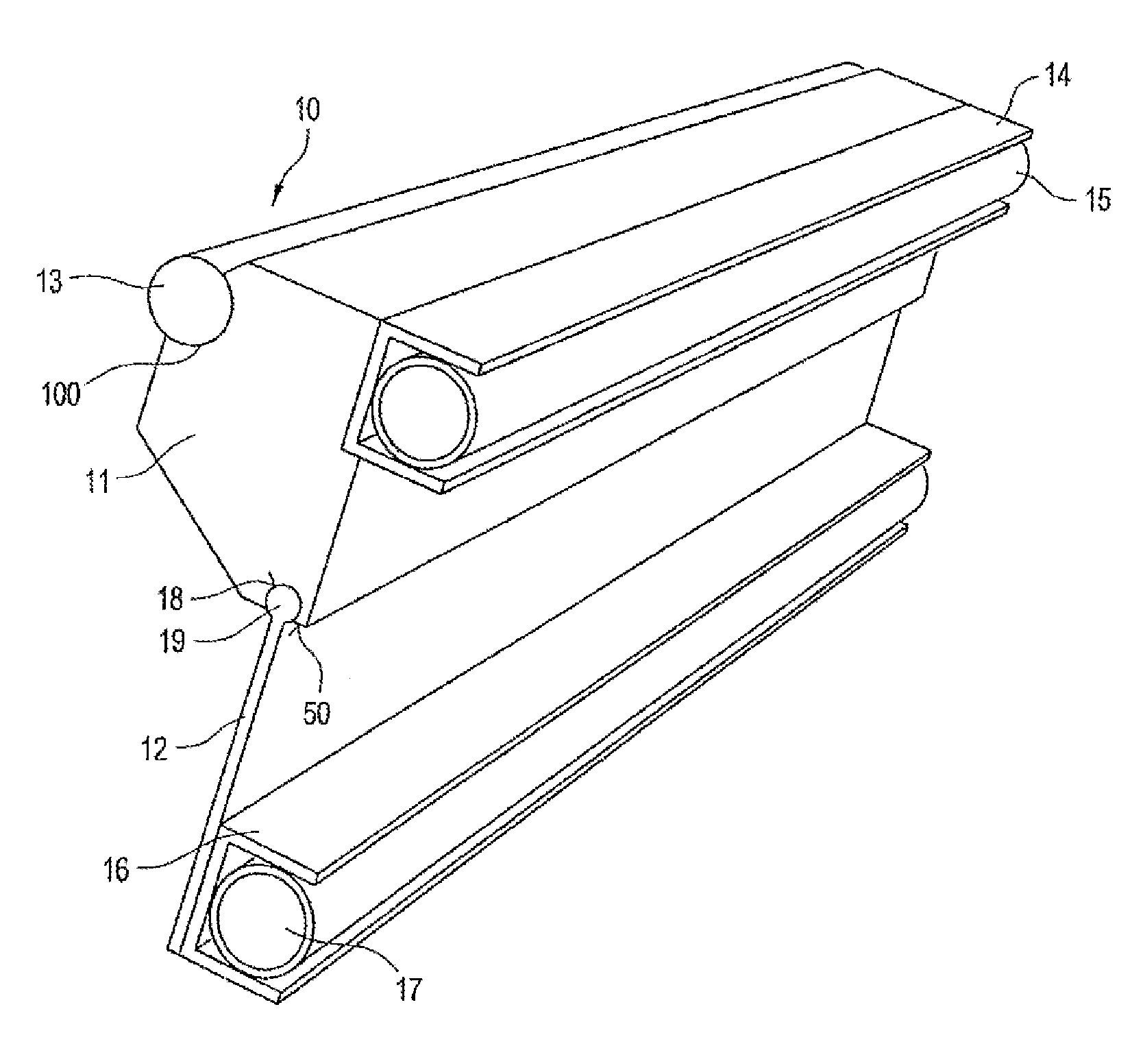
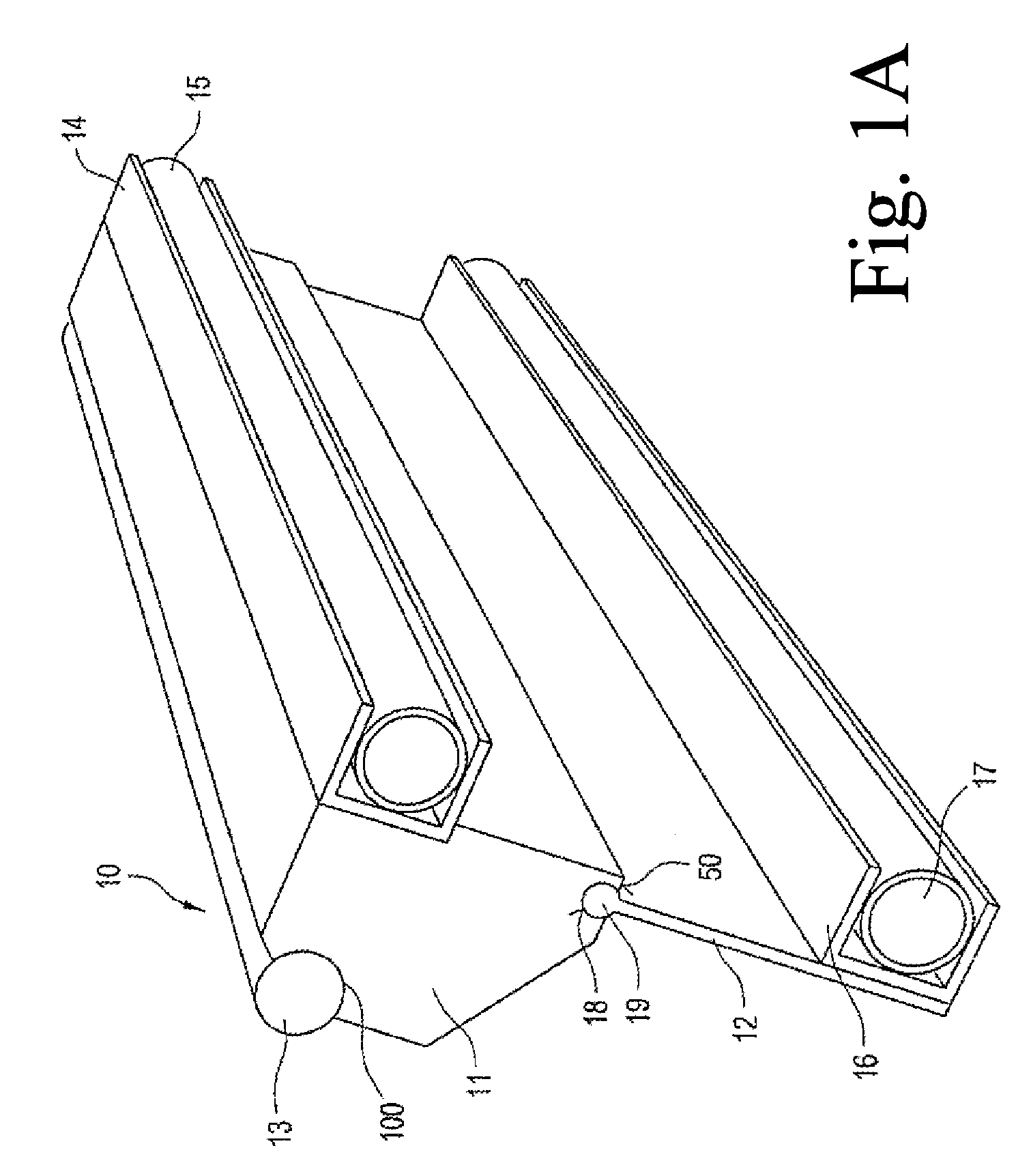
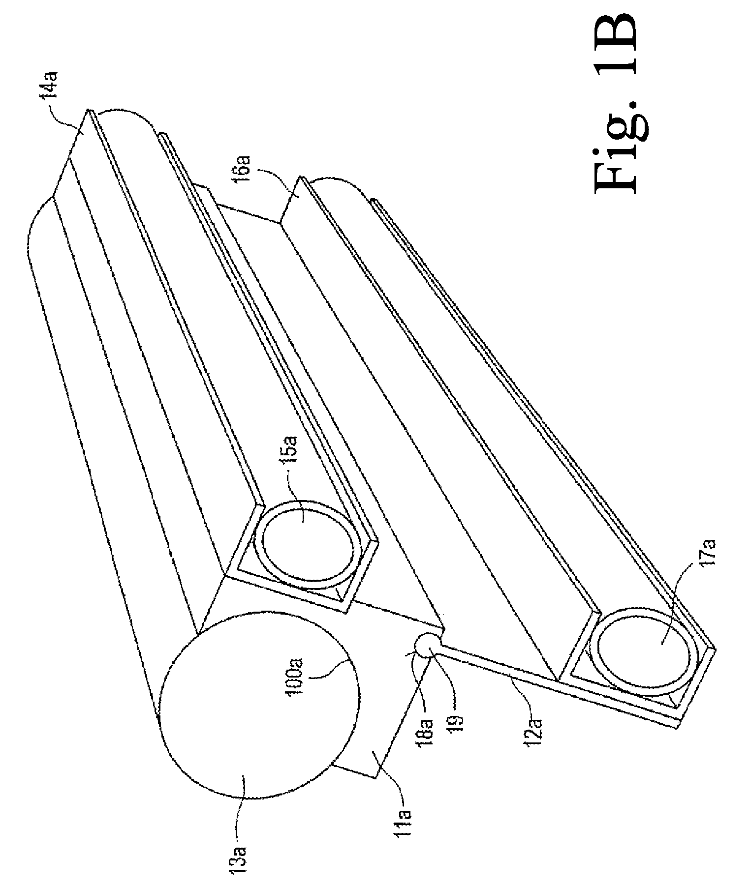
[0045]Referring now to the drawings, and more particularly to FIG. 1A, there is shown a doctor device 10 assembled in the manner of a module, having a top part 11 and a bottom part 12. The top part 11 is at the same time a holding part for a rotatable circularly cylindrical metering rod 13.

[0046]On the top part 11, a pressure tube 15 is inserted into a first holder 14. The pressure tube 15 presses the top part 11, including the rotatable metering rod 13 held therein, against a fibrous web, likewise not shown here.

[0047]On the bottom part 12, a clamping tube 17 is arranged in a second holder 16. By way of the clamping tube 17, the doctor device 10 is clamped firmly in a supporting element, not specifically illustrated here, and is to be designated “clamping foot”40.

[0048]The pressure tube 15 and the clamping tube 17 are therefore both fitted to the doctor device 10. Consequently, during cleaning work, they can be removed from the supporting element together with the doctor device 10,...


PUM


Abstract

The present invention relates to a doctor device for metering and / or leveling a liquid to pasty medium applied to a moving surface, the surface in the case of direct application being a paper, board or other fibrous web and in the case of indirect application being the surface of a transfer element which transfers the medium to the fibrous web. The doctor device includes a cylindrical metering rod and a pressure tube, with which the metering rod can be pressed against the moving surface for the purpose of metering and / or leveling the medium applied. Additionally, the doctor device is of modular design, having a top part and a bottom part, the top part being provided with a first holder for holding the pressure tube, and the bottom part being provided with a second holder for holding a clamping tube.

Description

CROSS REFERENCE TO RELATED APPLICATIONS[0001]This is a continuation of PCT application No. PCT / EP2005 / 052007, entitled “DOCTOR BLADE DEVICE”, filed May 3, 2005.BACKGROUND OF THE INVENTION[0002]1. Field of the Invention[0003]The invention relates to a doctor device for metering and / or leveling a liquid to pasty medium applied to a moving surface, the surface in the case of direct application of the medium being a paper, board or other fibrous web and in the case of indirect application being the surface of a transfer element which transfers the medium to the fibrous web.[0004]2. Description of the Related Art[0005]During the application, the application layer is normally applied in excess and therefore has to be doctored off to the desired coating weight, that is to say metered. On the other hand, if the application medium is applied exactly in the desired coating quantity, it merely has to be leveled or evened out by the doctor device, that is to say by a doctor element fitted in th...

Claims


Application Information

Patent Timeline
Patent Type & Authority Patents(United States)
IPC IPC(8): B05C11/02B05C1/00D21H25/10
CPCB05C11/025D21H25/10
Inventor HENNINGER, CHRISTOPHKAIPF, HORSTWOZNY, ECKARDSCHAUBMAIER, MARTINHEITZINGER, MICHAELKEINBERGER, RUDIGER
Owner VOITH PATENT GMBH
Why Eureka
Try Eureka